
A spraying equipment and spraying process for cylindrical parts

A spraying equipment, cylindrical technology, applied in the direction of coating, spraying device, device for coating liquid on the surface, etc., can solve the problem of paint body damage, etc., and achieve the effect of easy maintenance, practical maintenance, and avoiding direct contact

Active Publication Date: 2019-08-27
山东惠元新材料科技发展有限公司
View PDF5 Cites 2 Cited by
  • Summary
  • Abstract
  • Description
  • Claims
  • Application Information

AI Technical Summary

Problems solved by technology

[0003] Most of the existing spraying equipment is manually operated. If the operator does not operate properly, the paint will cause damage to the body.
In addition, with the development of industrial technology, pure handwork can no longer meet the needs of the market. Spraying has developed from manual to industrial automation, and the degree of automation is getting higher and higher. Therefore, the application of spraying production lines is becoming more and more extensive. Into many fields of the national economy
[0004] Moreover, the existing spraying equipment can only spray on one side of the mechanical parts, and cannot perform a full range of spraying operations

Method used


Image

  • A spraying equipment and spraying process for cylindrical parts
  • A spraying equipment and spraying process for cylindrical parts
  • A spraying equipment and spraying process for cylindrical parts

Examples


Embodiment Construction

[0046] The following will clearly and completely describe the technical solutions in the embodiments of the present invention with reference to the accompanying drawings in the embodiments of the present invention. Obviously, the described embodiments are only some, not all, embodiments of the present invention. Based on the embodiments of the present invention, all other embodiments obtained by persons of ordinary skill in the art without creative efforts fall within the protection scope of the present invention.

[0047] In the description of the present invention, it should be understood that the terms "upper", "lower", "bottom", "middle", "vertical", "inner", etc. indicate orientation or positional relationship, and are only for the convenience of describing the present invention. Inventive and simplified descriptions do not indicate or imply that the components or elements referred to must have a particular orientation, be constructed and operate in a particular orientatio...


PUM


Abstract

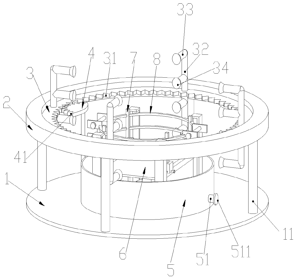
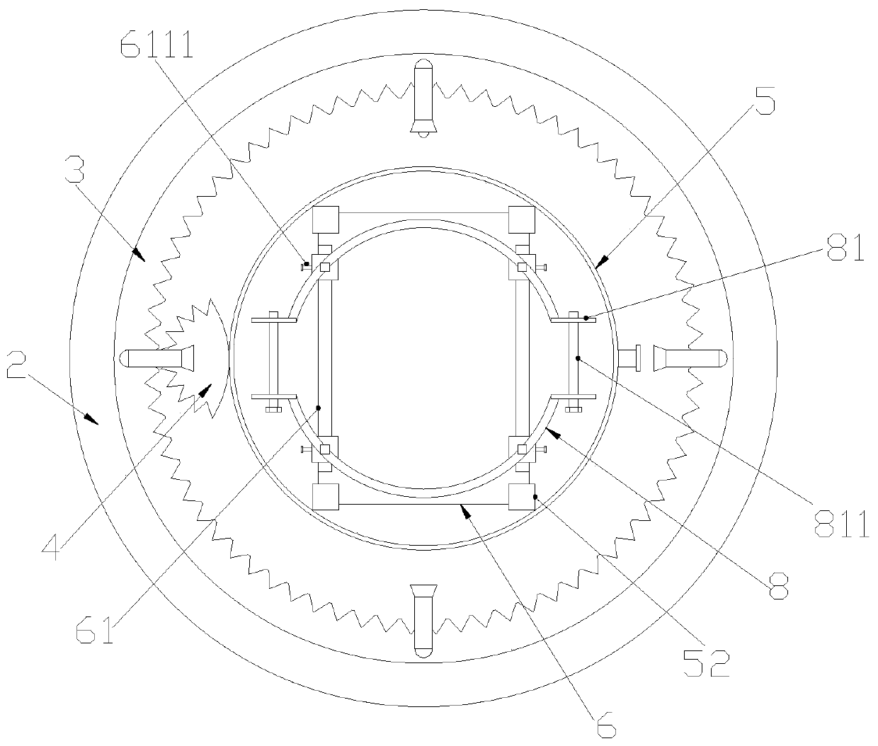
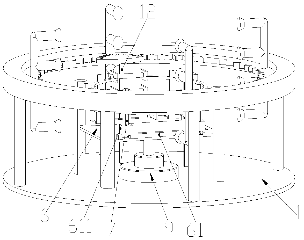
The invention discloses spraying equipment for cylindrical parts. The spraying equipment comprises a round base and is characterized in that supporting columns are arranged at the upper end of the base, and an annular fixing table is arranged at the upper ends of the supporting columns; a first sliding groove is formed in the inner side of the circumference of the annular fixing table, and a rotating table is installed in the first sliding groove; a rotating shaft is arranged at the upper end of the base, and a driving mechanism is fixed at the upper end of the rotating shaft; a collecting groove is formed in the upper end of the base; a fixing column is arranged at the bottom end of the collecting groove, and a second sliding groove is formed in the fixing column; a supporting table is arranged in the second sliding groove; sliding rails which are symmetrically distributed are arranged at the upper end of the supporting table, and sliding blocks are arranged on the sliding rails; fixing columns are arranged at the upper ends of the sliding blocks, and clamping grooves are formed in the fixing columns; and arc-shaped fixing rings are fixed in the clamping grooves. The invention aims to provide the spraying equipment for the cylindrical parts and the spraying process of the spraying equipment. A spraying pipe capable of rotating intermittently and a lifting clamping device are arranged on the device, so that full automation of spraying equipment is realized.

Description

technical field [0001] The invention relates to the technical field of surface thermal spraying, in particular to a spraying equipment for cylindrical parts and a spraying process thereof. Background technique [0002] Thermal spraying refers to a series of processes in which fine and dispersed metallic or non-metallic coating materials are deposited on the surface of a prepared substrate in a molten or semi-molten state to form a spray deposition layer. Coating materials can be in powder, ribbon, filament or rod form. The thermal spray gun provides the necessary heat from fuel gas, electric arc or plasma arc to heat the thermal spray material to a plastic or molten state, and then undergoes the acceleration of compressed air to make the confined particle beam impact on the surface of the substrate. The particles impacted on the surface are deformed by stamping to form laminated flakes, which adhere to the surface of the prepared substrate, then cool and pile up continuous...

Claims


Application Information

Patent Timeline
Patent Type & Authority Patents(China)
IPC IPC(8): B05B13/02B05B13/04B05B14/00B05D1/02B05D3/02
Inventor 陈益童白雪兰
Owner 山东惠元新材料科技发展有限公司
Learn More