Reflection window-based device and method for increasing terahertz wave imaging signal-to-noise ratio
A technology of terahertz wave imaging and terahertz wave off-axis, applied in the field of terahertz wave imaging, can solve the problems of large ratio of peak signal amplitude to noise level of time-domain data, difficulty in improving signal-to-noise ratio, and affecting imaging quality , to achieve the effect of improving the imaging signal intensity, improving the imaging signal-to-noise ratio, and improving the imaging quality
- Summary
- Abstract
- Description
- Claims
- Application Information
AI Technical Summary
Problems solved by technology
Method used
Image
Examples
Embodiment 1
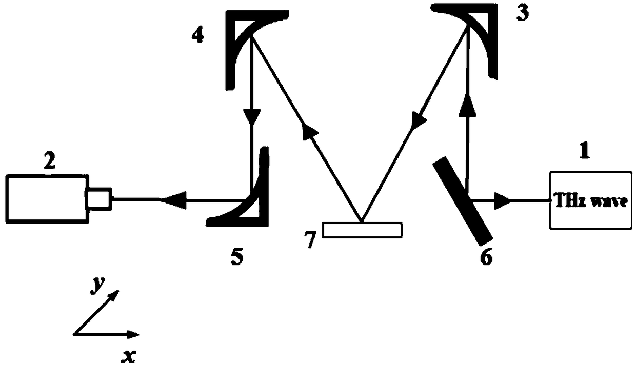
[0047] An embodiment of the present invention provides a device for improving the signal-to-noise ratio of terahertz wave imaging based on the reflection window, see figure 1 , the device includes: a terahertz radiation source 1, a detector 2 receiving the terahertz radiation source, a first terahertz wave off-axis parabolic mirror 3, a second terahertz wave off-axis parabolic mirror 4, a third terahertz wave off-axis parabolic mirror a parabolic mirror 5, a terahertz wave plane mirror 6, and a reflection window 7,
[0048] Wherein, the reflective window 7 is a material highly transparent to terahertz waves, which is fixed on the two-dimensional scanning platform for placing the imaging sample to be measured;
[0049] The terahertz wave plane reflector 6, the first terahertz wave off-axis parabolic mirror 3, the second terahertz wave off-axis parabolic mirror 4, and the third terahertz wave off-axis parabolic mirror 5 are sequentially arranged on the outgoing light path of the...
Embodiment 2
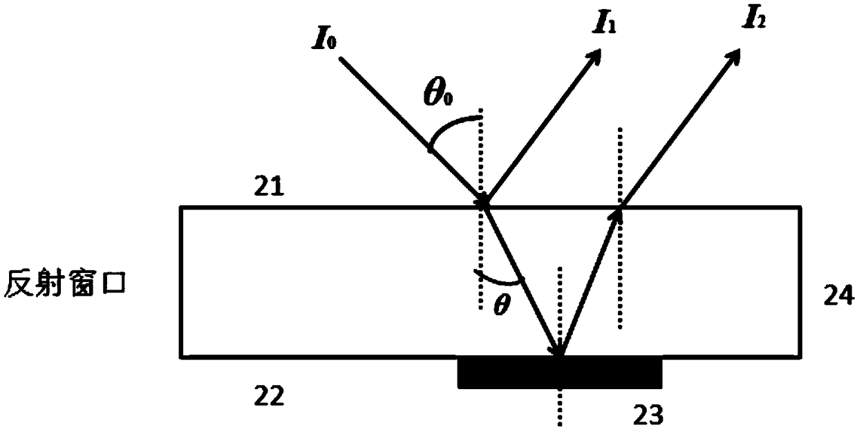
[0059] An embodiment of the present invention provides a method for improving the signal-to-noise ratio of terahertz wave imaging based on a reflection window, and the method is realized by using a reflection window. Since the signal strength of the terahertz wave reflected multiple times in the reflection window decreases gradually, the signal received by the terahertz wave reflective imaging only considers the terahertz wave reflected for the first time by the first reflection window surface 21 and the second reflection window surface 22 composition, i.e. I 1 and I 2 , the optical path diagram of the terahertz wave in the reflection window, such as figure 2 shown.
[0060] Among them, I 0 is the angle of incidence θ 0 The incident intensity of the terahertz wave, I 1 is the incident light I 0 The reflected light intensity at the first reflective window surface 21, I 2 is the reflected light intensity of the incident light transmitted through the first reflective wind...
Embodiment 3
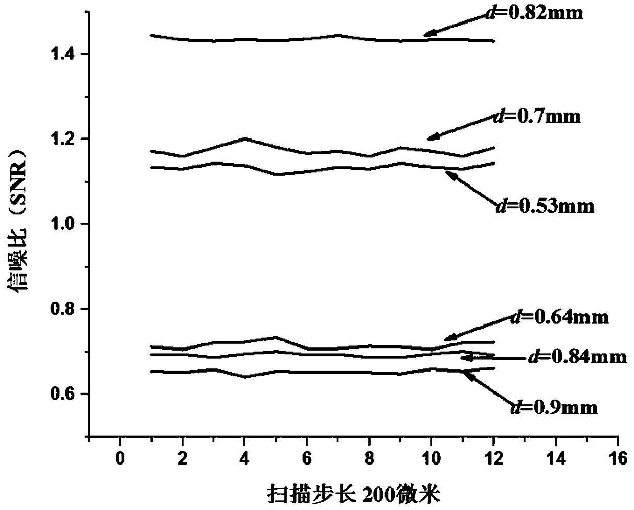
[0073] Combine below image 3 Carry out feasibility verification to the scheme, working principle in embodiment 1, see the following description for details:
[0074] The purpose of the embodiments of the present invention is to provide a method for improving the imaging signal-to-noise ratio and reducing the influence of external noise on terahertz wave reflective imaging during the data acquisition stage.
[0075] In this example, the reflective imaging signal-to-noise ratio is calculated by applying reflective windows with different thicknesses to scan and image the gold-plated reflector. When the terahertz frequency is 2.52THz, the signal-to-noise ratio of a horizontal line scanning on the gold-plated mirror, such as image 3 shown.
[0076] Terahertz source produces terahertz wave output, terahertz wave (intensity is I 0 ) with θ 0 The angle is incident on the first reflection window surface 21, and a part of the terahertz wave is reflected by the first reflection win...
PUM
 Abstract
Description
Claims
Application Information
 - R&D
- Intellectual Property
- Life Sciences
- Materials
- Tech Scout
- Unparalleled Data Quality
- Higher Quality Content
- 60% Fewer Hallucinations
Browse by: Latest US Patents, China's latest patents, Technical Efficacy Thesaurus, Application Domain, Technology Topic, Popular Technical Reports.
© 2025 PatSnap. All rights reserved.Legal|Privacy policy|Modern Slavery Act Transparency Statement|Sitemap|About US| Contact US: help@patsnap.com


