
Direct current feedback electronic load

A technology of electronic load and feedback circuit, which is applied in the field of DC feedback electronic load

Pending Publication Date: 2019-03-12
四川太牛电子科技有限公司
View PDF0 Cites 3 Cited by
  • Summary
  • Abstract
  • Description
  • Claims
  • Application Information

AI Technical Summary

Problems solved by technology

[0003] Aiming at the above-mentioned deficiencies in the prior art, the DC feedback electronic load provided by the present invention overcomes the defects of existing electronic load products, and provides an energy feedback electronic load, which is used for various power supplies and chargers. Experimental new power electronic device capable of simulating various mobile phone charging and resistive load characteristics

Method used

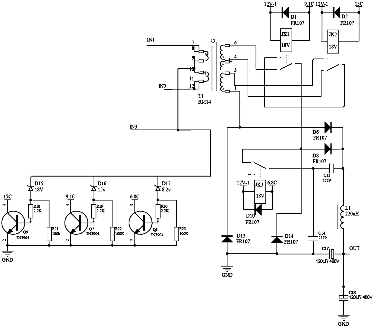
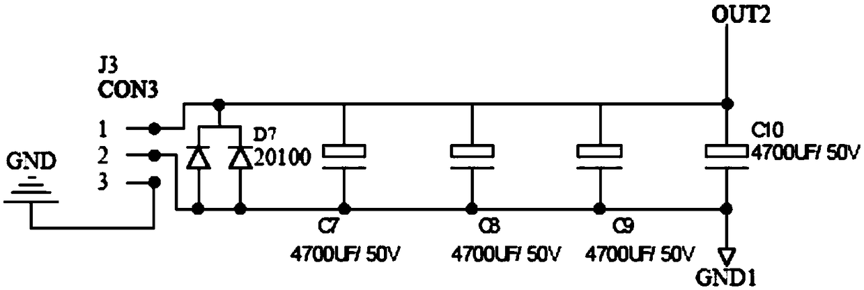

Image

  • Direct current feedback electronic load
  • Direct current feedback electronic load
  • Direct current feedback electronic load

Examples


Embodiment Construction

[0074] The specific embodiments of the present invention are described below so that those skilled in the art can understand the present invention, but it should be clear that the present invention is not limited to the scope of the specific embodiments. For those of ordinary skill in the art, as long as various changes Within the spirit and scope of the present invention defined and determined by the appended claims, these changes are obvious, and all inventions and creations using the concept of the present invention are included in the protection list.

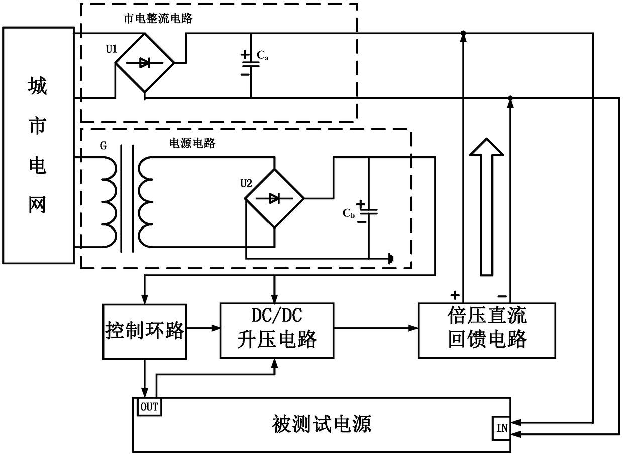
[0075] Such as figure 1 As shown, a DC feedback electronic load includes a mains rectification circuit, a power supply circuit, a control loop, a DC / DC boost circuit, a voltage doubler DC feedback circuit and a power supply under test;

[0076] Both the mains rectification circuit and the power supply circuit are connected to the city power grid, and the mains rectification circuit is also respectively connected to the volt...


PUM


Abstract

The invention discloses a direct current feedback electronic load. The direct current feedback electronic load comprises a mains supply rectifying circuit, a power supply circuit, a control loop, a DC / DC booster circuit, a voltage-multiplying direct current feedback circuit, a mains supply synchronous drive DC / AC circuit and a tested power supply. The direct current feedback electronic load overcomes the defects of existing electronic load products and is a novel power electronic device which is used for delivery tests of various power supplies and chargers and can simulate the charging and resistance load characteristics of various mobile phones; the direct current feedback electronic load can achieve stepless regulation of a simulated resistance value and the regeneration and utilizationof electric energy and has the advantages of being capable of saving the energy, free of high-frequency interference, small in size, low in weight, capable of saving the installation space, excellentin test performance and the like.

Description

technical field [0001] The invention belongs to the technical field of electronic loads, and in particular relates to a DC feedback electronic load. Background technique [0002] With the rapid development of electronic technology, there are more and more portable electronic products with more and more powerful functions and greater power consumption. Such as mobile phones, digital cameras, DV, tablet PCs and electric vehicles, etc., in order to get a longer use time, the capacity of the rechargeable battery can only be increased, so that the charging time of electronic products is getting longer and longer, which is unacceptable . Therefore, major manufacturers have launched fast charging technologies one after another to solve the problem of too long charging time. Since the fast charging technologies and protocols of major manufacturers are different and incompatible with each other, it brings inconvenience, economic burden and waste of resources to users. It also puts ...

Claims


Application Information

Patent Timeline
Patent Type & Authority Applications(China)
IPC IPC(8): G01R31/40
CPCG01R31/40
Inventor 陈开荣陈开新陈宗映
Owner 四川太牛电子科技有限公司
Learn More