A bonding method of a display device and a fingerprint module

A fingerprint module and display device technology, applied in character and pattern recognition, static indicators, data processing input/output process, etc., can solve the problem of high cost of display devices, and save special machines and corresponding bonding Process, the effect of reducing production costs

Active Publication Date: 2019-03-12
BOE TECH GRP CO LTD +1
View PDF3 Cites 12 Cited by
  • Summary
  • Abstract
  • Description
  • Claims
  • Application Information

AI Technical Summary

Problems solved by technology

[0005] In order to solve the above-mentioned technical problems, an embodiment of the present invention provides a bonding method of a display device and a fingerprint module to solve the integration and bonding method of the fingerprint module i

Method used


Image

  • A bonding method of a display device and a fingerprint module
  • A bonding method of a display device and a fingerprint module
  • A bonding method of a display device and a fingerprint module

Examples


Embodiment Construction

[0035] In order to make the purpose, technical solution and advantages of the present invention more clear, the embodiments of the present invention will be described in detail below in conjunction with the accompanying drawings. It should be noted that, in the case of no conflict, the embodiments in the present application and the features in the embodiments can be combined arbitrarily with each other.

[0036] The following specific embodiments provided by the present invention can be combined with each other, and the same or similar concepts or processes may not be repeated in some embodiments.

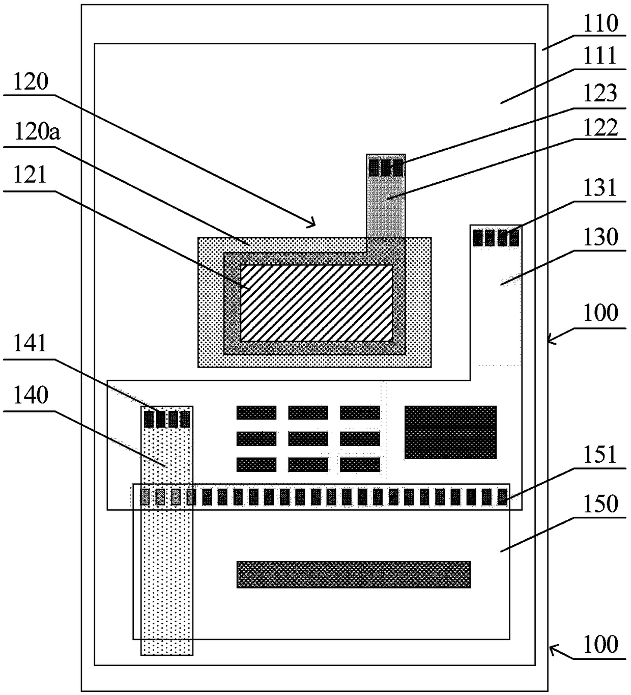
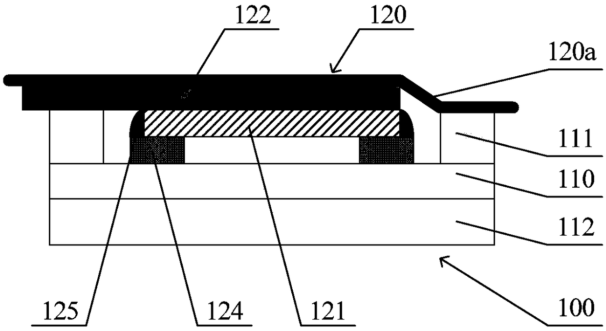
[0037] figure 1 It is a schematic diagram of the overall structure of a display device in the prior art, figure 2 for figure 1 Schematic diagram of the partial structure of the display device shown. figure 1 The display device 100, the display panel 110, the fingerprint module 120, the MFPC 130 and its connector 131, the TFPC 140 and its connector 141, the Chip On FPC (COF for ...


PUM


Abstract

The embodiment of the invention discloses a bonding method of a display device and a fingerprint module. The display device comprises a display panel, a fingerprint module and a functional flexible circuit board FPC. A colloidal film is attached to the side of the display panel away from the light emitting surface, and an opening area is arranged in the colloidal film. A functional FPC is attachedto the side of the display panel away from the light emitting surface through a scattering film. The fingerprint module is arranged on the side of the functional FPC close to the display panel, and the fingerprint module is embedded in the opening area of the gelatin film through the functional FPC. The embodiment of the invention solves the problem of high cost of the display device due to the need of additional special FPC carrier and the need of using a special machine to execute additional device mounting process in the integration and bonding mode of the fingerprint module in the prior display device.

Description

technical field [0001] The present application relates to but is not limited to the fields of display technology and fingerprint technology, and especially refers to a bonding method of a display device and a fingerprint module. Background technique [0002] As a commonly used means of identification, fingerprint recognition technology has become the standard configuration of mobile terminal equipment such as mobile phones. With the development of full-screen technology, the fingerprint recognition module of display devices such as mobile phones is gradually transferred to the back of the display screen to simultaneously realize fingerprint recognition under the screen and full-screen display. [0003] In the prior art, the way of integrating and bonding the fingerprint identification module in the display screen is usually: firstly, the chip, sensor, connector and its auxiliary components of the fingerprint module are fabricated on a dedicated flexible printed circuit (FPC ...

Claims


Application Information

Patent Timeline
IPC IPC(8): G06K9/00G06V10/147G06V40/13
CPCG06V40/13G06F1/1684H05K3/323H05K1/189H05K2201/10128H05K2201/10151G06F1/1626G06F1/1637G06V10/147G06F3/0412G06F3/0416G09G3/20H05K1/028
Inventor 易利祥肖枫郭浩清
Owner BOE TECH GRP CO LTD
Why Eureka
Try Eureka