Dual-band micro-strip grid array antenna

A grid array, dual-band technology, applied in specific array feeding systems, antennas, antenna arrays, etc., can solve problems such as no dual-band application work, and achieve the effect of small physical size

Inactive Publication Date: 2019-03-12
SHANGHAI JIAO TONG UNIV
View PDF3 Cites 8 Cited by
  • Summary
  • Abstract
  • Description
  • Claims
  • Application Information

AI Technical Summary

Problems solved by technology

There has been extensive work reported on grid array antennas, however no work has been reported on dual-band applications

Method used


Image

  • Dual-band micro-strip grid array antenna
  • Dual-band micro-strip grid array antenna
  • Dual-band micro-strip grid array antenna

Examples


Embodiment 1

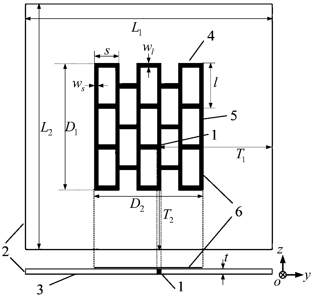
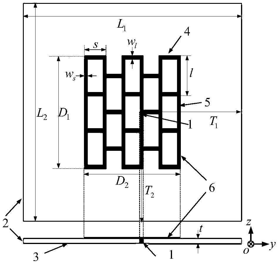
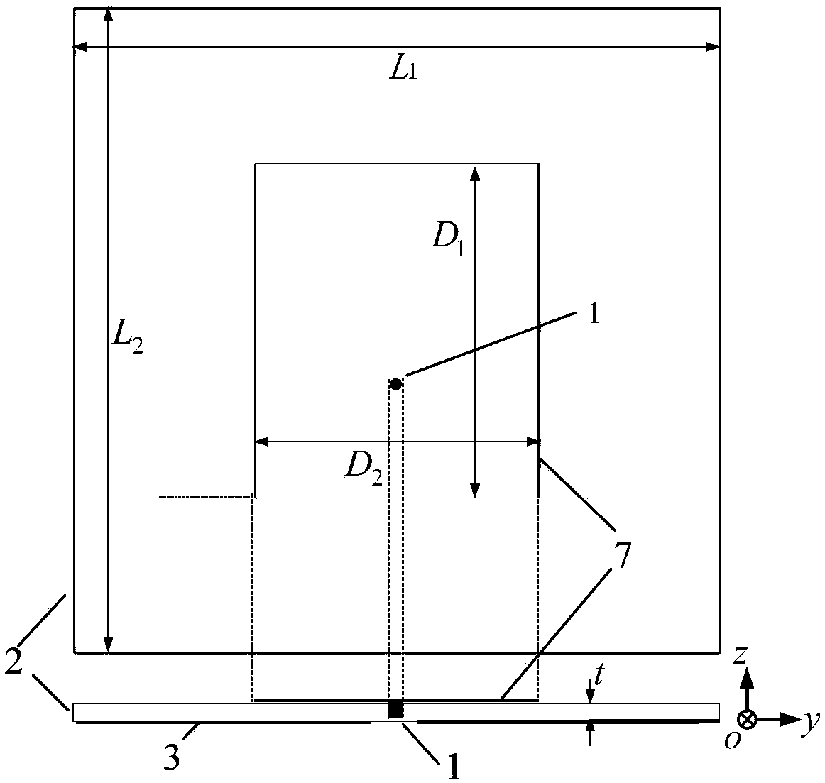
[0081] For the multi-band wireless communication system working antenna, this embodiment designs a dual-band microstrip grid array antenna, which can be used in the wireless communication system. The antenna covers two frequency bands, and can also be optimized to cover specific frequency bands. The antenna mainly includes structures such as a radiator, a dielectric base metal ground plane, and a coaxial feed.

[0082] The antenna radiator has a rectangular structure of multiple microstrip lines, which are intersected and staggered. The unit of the grid array is composed of two short sides and two long sides. In the high frequency band, the electrical length of the short side is about half of the high frequency resonant wavelength, and the long side is about the resonant wavelength. The long side plays the role of transmitting current, and the short side is used for radiation. In the low frequency band, the total electrical length of the long side of the grid array in the d...


PUM


Abstract

The invention provides a dual-band micro-strip grid array antenna. The antenna comprises an antenna radiation body, a dielectric substrate and a ground plane; the radiation body is arranged on the upper surface of the dielectric substrate in parallel; and the ground plane is arranged on the lower surface of the dielectric substrate in parallel. On the basis of an original grid array antenna, the position of a feed point is changed, and two working modes can be stimulated, so that dual bands are realize; and the radiation body of the antenna also has the advantages of being small in physical size, integrated and the like.

Description

technical field [0001] The present invention relates to the technical field of antennas, in particular to a dual-band microstrip grid array antenna. Background technique [0002] The current wireless communication technology is developing rapidly to meet people's demand for information. As an indispensable device in the wireless communication system, the antenna is also developing in the direction of miniaturization, integration and multi-function (multi-band, multi-polarization and multi-purpose). The multi-band operation of the antenna can reduce the use of a large number of antennas, thereby reducing the size of the wireless communication system. There are also a lot of work in the direction of multi-band antennas at home and abroad. The invention improves the grid array antenna and applies it to dual frequency bands. There has been extensive work reported on grid array antennas, however no work has been reported for dual-band applications. Contents of the invention ...

Claims


Application Information

Patent Timeline
Patent Type & Authority Applications(China)
IPC IPC(8): H01Q21/00H01Q1/48H01Q1/36H01Q1/50H01Q5/10H01Q5/307H01Q5/50
CPCH01Q1/36H01Q1/48H01Q1/50H01Q5/10H01Q5/307H01Q5/50H01Q21/00H01Q21/0006
Inventor 徐光辉彭宏利张跃平尹文言
Owner SHANGHAI JIAO TONG UNIV
Why Eureka
Try Eureka