Cup assembly and food high-speed blender

A cooking machine and component technology, applied in cooking utensils, household utensils, applications, etc., can solve the problems of large workload of the drive device, increased cup thickness, low crushing efficiency, etc., to improve processing efficiency, reduce contact distance, Energy Saving Effect

Pending Publication Date: 2019-03-15
黄文雄
View PDF3 Cites 4 Cited by
  • Summary
  • Abstract
  • Description
  • Claims
  • Application Information

AI Technical Summary

Problems solved by technology

The spoiler ribs are integrally formed with the cup body, which further increases the thickness and weight of the cup body, and this cup body needs a special mold for production, which leads to high manufacturing costs
On the other hand, due to the large distance between the cutter and the spoiler, the contact probability between the food and the cutter is reduced, and the crushing efficiency is low. If the size of the cutter is increased, the work load of the drive device will be large, and a drive with high power is required. The device can meet the requirements, resulting in high manufacturing cost of the whole machine

Method used


Image

  • Cup assembly and food high-speed blender
  • Cup assembly and food high-speed blender
  • Cup assembly and food high-speed blender

Examples


Embodiment 1

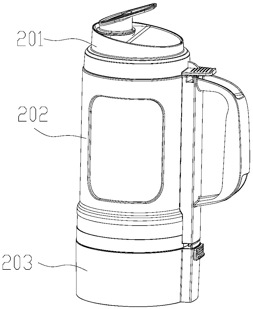
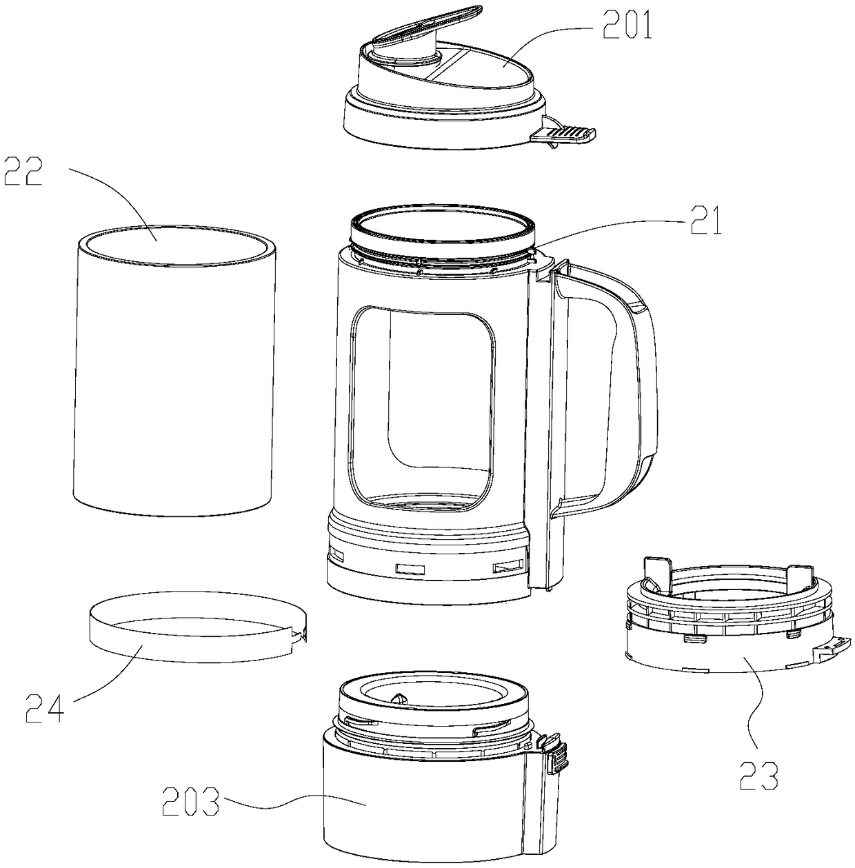
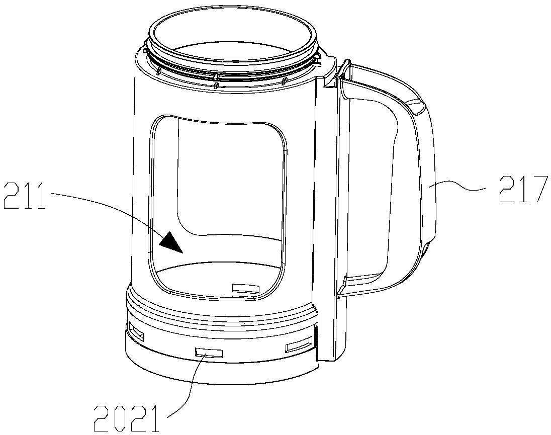
[0046] see Figure 1 to Figure 18 , the cup assembly 2, which includes a lid 201, a cup body 202 and a cup holder 203, the cup holder 203 is sealed and connected to the lower end of the cup body 202, the lid 201 is installed on the upper end of the cup body 202 for opening and closing the inner cavity of the cup body 202, and the cup holder 203 is provided with a cutter assembly 204 and a heating device 205, the cup holder 203 is provided with a stirring chamber 2031 passing through the inner cavity of the cup body 202, and the side wall of the stirring chamber 2031 is provided with a number of vertical first spoiler ribs 2032, the cutter assembly 204 is installed in the stirring chamber 2031.

[0047] Compared with the prior art, the cup assembly 2 provided by the present invention can reduce the contact distance between the cutter assembly 204 and food by setting the stirring chamber 2031 in the stirring chamber 2031, which can effectively improve the processing efficiency a...

Embodiment 2

[0090] see Figure 23 The main difference between this embodiment and Embodiment 1 is that the glass inner cup 22 is a double-layer glass, which includes a first cup body 221 on the outer layer and a second cup body 222 on the inner layer. The second cup body 222 is provided with a second spoiler rib 223 arranged vertically, the first cup body 221 is a cylindrical structure, and the two ends of the first cup body 221 and the second cup body 222 are connected into one body through a welding process. By adopting the structure of double-layer glass, a layer of first cup body 221 is welded outside the second cup body 222, so that the glass inner cup 22 forms a cylindrical shape, so that there is no gap between the glass inner cup 22 and the cup shell when installed. The gap provides better protection for the glass inner cup, and solves the assembly requirements of the glass inner cup 22 and the cup shell 21 and the technical requirements for setting the second spoiler rib 223 . I...


PUM


Abstract

The invention provides a cup assembly and a food high-speed blender with the cup assembly. The cup assembly comprises a cover, a cup body and a cup seat. The cup seat is in seal connection to the lower end of the cup body, the cover is mounted at the upper end of the cup body, a stirring cavity passing through an inner cavity of the cup body is formed in the cup seat, multiple vertically-arrangedfirst turbulence ribs are arranged on the side wall of the stirring cavity, and a tool assembly is mounted in the stirring cavity. Compared with the prior art, the cup assembly is provided with the stirring cavity, the contact distance between the tool assembly and food can be shortened in the stirring cavity, the processing efficiency can be effectively improved, and the energy consumption can bereduced. On the other hand, the turbulence rib structures on the cup assembly can be selectively removed, and the structure of the cup assembly is simplified.

Description

technical field [0001] The invention relates to the technical field of food cooking equipment, in particular to a cup assembly of a food wall-breaking cooking machine and a food wall-breaking cooking machine. Background technique [0002] The working principle of the food breaking machine is to rely on the high-speed rotation of the knife at the bottom of the mixing cup. Under the action of the water flow, the food is repeatedly broken, breaking the food cell wall, releasing the nutrients in the cells, so that the food can be absorbed by the gastrointestinal tract. and better digestion. Compared with ordinary blenders, because the food wall-breaking cooking machine can better break down the ingredients and make full use of the nutrition of the food, it is deeply loved by people. [0003] Existing food-breaking cooking machines generally include a host and a cup assembly. The cup assembly is detachably mounted on the host. The cup assembly includes a lid, a cup body and a cu...

Claims


Application Information

Patent Timeline
Patent Type & Authority Applications(China)
IPC IPC(8): A47J43/07A47J43/046A47J27/00
CPCA47J27/004A47J43/046A47J43/0716A47J43/0727
Inventor 不公告发明人
Owner 黄文雄
Why Eureka
Try Eureka