Devices and methods for treating lung tumors
A technology of lung tissue and conductive fluid, which is applied in parts of surgical instruments, surgical instruments for suctioning substances, medical science, etc., can solve the problems of slow development and lack, and achieve the effect of expanding the scope and reducing tissue impedance
- Summary
- Abstract
- Description
- Claims
- Application Information
AI Technical Summary
Problems solved by technology
Method used
Image
Examples
Embodiment 1
[0092] Embodiment 1 (cylindrical ablation electrode)
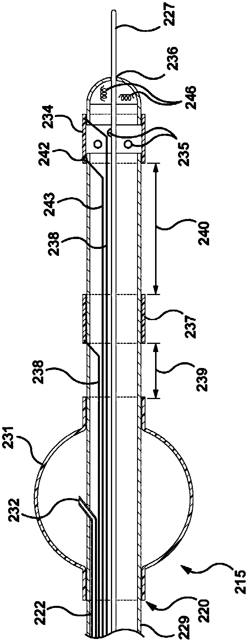
[0093] image 3 An example of a device 220 is shown that can be delivered from within a working tube for occluding and atelectrating a target lung segment, injecting conductive fluid into the target lung segment, monitoring the state of tissue properties, and ablating tumors. Figure 4 expressed image 3 The situation of the device in the actual application.
[0094]The device 220 has an elongate cannula 229, the proximal end of which should remain outside the patient's body and the distal portion 215 of which should be delivered from the working conduit to the target lung area close to the target lung tumor. The distal portion 215 can be delivered through a working tube, such as the working tube 225 of the bronchoscope 221, or the cannula 213 that can be delivered from the working tube of the bronchoscope. During delivery, the maximum outer diameter of the device should be smaller than the inner diameter of the working...
Embodiment 2
[0109] Embodiment 2 (needle electrode)
[0110] or, as in Figure 5 and Figure 6 shown, similar to image 3 or Figure 4 The embodiment of the radio frequency electrodes 234 shown in , at least one of which can be a needle electrode 250, is used to puncture the wall of the airway, and the radio frequency electrodes are placed in the target tumor 80, or in the adjacent lung tissue. The needle electrode 250 may include an irrigation port 251 for fluid communication with the irrigation lumen through the cannula 229 and extending across the proximal end of the cannula device. The length of the needle electrode 250 can be in the range of 5 mm to 10 mm (eg, 6 mm to 8 mm, 7 mm), and the diameter can be in the range of 0.1 mm to 1.7 mm (eg, 1.5 mm). Alternatively, the needle electrode may comprise a guide wire lumen 252 (eg, inner diameter may range from 0.38 mm to 0.76 mm), allowing the device to be delivered over a guide wire. The tip 253 of the needle electrode 250 can be sharp...
Embodiment 3
[0116] Embodiment 3 (multiple ablation sleeves)
[0117] Figure 7 An example is shown of two cannulae 100 and 101 containing energy delivery electrodes 102 and 103 , which can be deployed with a flexible bronchoscope 221 , respectively, and place the electrodes in the airway at both ends of the target tumor 80 . The device may comprise a closure sheath 270 that may be delivered through the working tube 225 of the bronchoscope 221 , or through the delivery cannula 213 . The closure sleeve 270 may include a filling device 271 such as a compliant balloon that may be placed over the closure sleeve 270 . A filling lumen deploys or fills the filling device 271 by passing within the closure sleeve and exiting the port 272 within the filling device. The closure sleeve 270 may contain two or more ablation lumens 273 and 274 with the outlet located distal to the filling device 271 . Other conceived forms of the closure element are also mentioned in the embodiments of the present inv...
PUM
| Property | Measurement | Unit |
|---|---|---|
| Conductivity | aaaaa | aaaaa |
| Diameter | aaaaa | aaaaa |
| Length | aaaaa | aaaaa |
Abstract
Description
Claims
Application Information
 - R&D
- Intellectual Property
- Life Sciences
- Materials
- Tech Scout
- Unparalleled Data Quality
- Higher Quality Content
- 60% Fewer Hallucinations
Browse by: Latest US Patents, China's latest patents, Technical Efficacy Thesaurus, Application Domain, Technology Topic, Popular Technical Reports.
© 2025 PatSnap. All rights reserved.Legal|Privacy policy|Modern Slavery Act Transparency Statement|Sitemap|About US| Contact US: help@patsnap.com


