Strip material segmenting equipment

A technology of cutting and equipment, applied in the direction of winding strip, thin material processing, metal processing, etc., can solve the problems of low segmentation accuracy, low cutting frequency, low efficiency of manual cutting, etc., to ensure the transmission effect, guarantee The effect of reliability

Active Publication Date: 2019-03-15
聊城市汉拯信息科技有限公司
View PDF5 Cites 1 Cited by
  • Summary
  • Abstract
  • Description
  • Claims
  • Application Information

AI Technical Summary

Problems solved by technology

[0002] In the field of processing and production, there are many types of materials that need to be processed in sections. In the field of food processing, there are also many situations that need to be processed in batches of strips or flakes. Currently, the commonly used methods for section processing are The method of mechanical equipment cutting and manual cutting. Manual cutting is low in efficiency, consumes a lot of manpower, and the segmentation accuracy is low. It can be used for processing a small amount of products with low precision requirements, but it is difficult to supply large quantities of products. According to the segmental processing work requirements, the common method of mechanical equipment segmenting is to use the crankshaft to drive the cutter to cut, but the cutting frequency is low, and the continuous transmission process of the equipment is insufficient. Now a special equipment for material segmenting is needed. solve the above problems

Method used


Image

  • Strip material segmenting equipment
  • Strip material segmenting equipment
  • Strip material segmenting equipment

Examples


Embodiment Construction

[0014] The following will clearly and completely describe the technical solutions in the embodiments of the present invention with reference to the accompanying drawings in the embodiments of the present invention. Obviously, the described embodiments are only some, not all, embodiments of the present invention. Based on the embodiments of the present invention, all other embodiments obtained by persons of ordinary skill in the art without making creative efforts belong to the protection scope of the present invention.

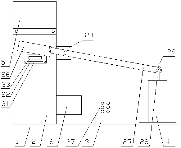
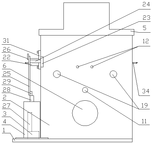
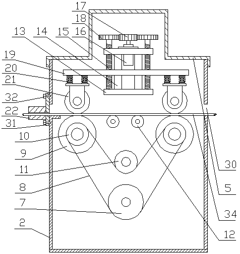
[0015] see Figure 1-3 , the present invention provides a technical solution: a strip material cutting equipment, including a base 1, the base 1 is equipped with a body shell 2, a wiring seat 3 and a cylinder 4, and the top of the body shell 2 is detachably connected with a On the upper cover 5, a stepping motor 6 is installed on one side of the body shell 2, and the stepping motor 6 cooperates with the driving pulley 7 installed inside the body shell 2, and t...


PUM


Abstract

The invention discloses strip material segmenting equipment. The strip material segmenting equipment comprises a base; a machine body outer shell, a wiring base and a cylinder are mounted on the base;a stepper motor is mounted at one side part of the machine body outer shell; the stepper motor is matched with a driving belt wheel mounted in the machine body outer shell; a lead screw base is mounted in the machine body outer shell; multiple guide columns and lead screws are mounted on the lead screw base; an adjusting motor is mounted at the middle part of the lead screw base, and is matched with a driving gear; the guide columns and the lead screws are both matched with an adjusting base; the front part of the machine body outer shell is detachably connected with a discharge base; a shaftbase is arranged on one side of the machine body outer shell, and is rotationally matched with a cutter rod through a cutter rod shaft; and a tool bit is detachably connected to one end of the cutterrod. The strip material segmenting equipment can continuously segment strips to achieve high segmenting efficiency, and is convenient to operate, high in safety, stable in feeding operation and difficult to slip and remove materials.

Description

technical field [0001] The invention relates to the field of mechanical cutting equipment, in particular to a long material cutting equipment. Background technique [0002] In the field of processing and production, there are many types of materials that need to be processed in sections. In the field of food processing, there are also many situations that need to be processed in batches of strips or flakes. Currently, the commonly used methods for section processing are The method of mechanical equipment cutting and manual cutting. Manual cutting is low in efficiency, consumes a lot of manpower, and the segmentation accuracy is low. It can be used for processing a small amount of products with low precision requirements, but it is difficult to supply large quantities of products. According to the segmental processing work requirements, the common method of mechanical equipment segmenting is to use the crankshaft to drive the cutter to cut, but the cutting frequency is low, a...

Claims


Application Information

Patent Timeline
Patent Type & Authority Applications(China)
IPC IPC(8): B26D1/30B65H20/02
CPCB26D1/30B26D1/305B65H20/02B65H2701/1133
Inventor 方胜
Owner 聊城市汉拯信息科技有限公司
Why Eureka
Try Eureka