Ultrasound-based non-destructive measurement method of intensity and position of internal heat source
A technology of heat source intensity and measurement method, which is applied in the direction of using sound wave/ultrasonic wave/infrasonic wave to analyze solids, instruments, and analysis materials, etc., which can solve problems such as height instability, unsatisfactory stability, and difficulty in meeting expectations in stability and accuracy. Achieve the effects of simplified measuring device, large measuring range and easy operation
- Summary
- Abstract
- Description
- Claims
- Application Information
AI Technical Summary
Problems solved by technology
Method used
Image
Examples
Embodiment 1
[0030] The measured component is a cuboid with a length of 0.1m, and a single point heat source Q=1e+6W / m is set at the center 3 , which is theoretically approximated as a one-dimensional heat transfer problem with an internal heat source.
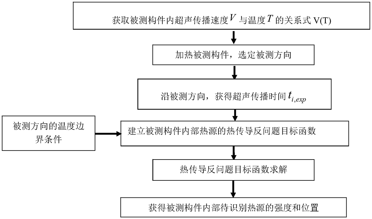
[0031] Step 1: Obtain the correlation between the ultrasonic propagation velocity V in the tested component and the temperature T under different temperature conditions, and fit the relationship between V and T V(T), where T is the condition that the overall temperature of the tested piece is consistent The temperature value under;
[0032] Step 2: Select the length direction as the measured direction, set it as the x direction, L is the length of the tested piece along the measured direction, L=0.1m; install heat insulation along the length direction except the upper and lower surfaces Layer, heating from one end of the member under test at x=0 along the direction of the test direction x, until the temperature of the heated end at x=0 of...
Embodiment 2
[0045] Embodiment 2: The measured component is a cuboid, the length is 1m, and the width is 0.1m. Two point heat sources are set, and the length direction is set as the x direction, wherein the central position of the cuboid is set at x=0.5m and y=0.05m. Point heat source Q=1e+6W / m 3 , set point heat source Q=1.2e+6W / m at the position 0.3m away from the end face of x=0, that is, x=0.3m, y=0.05m 3 . Set the width direction, that is, the y direction as the detection direction, heat from one end of the component under test at y=0, place the ultrasonic probe on the end face of y=1m, excite pulsed ultrasonic waves in the vertical incidence mode, and move the ultrasonic probe along the x direction , carry out stepping ultrasonic scanning detection, and follow the above steps 1 to 6 in turn, based on the change of the measured bottom echo propagation time, by solving the heat conduction inverse problem of the heat source, the intensity and position of the two internal heat sources a...
Embodiment 3
[0046] Embodiment 3: Same as the measured component of Embodiment 1, a single point heat source Q(t)=133928.57t is set at the central position 2 +1848214.29t+9250000. Place the ultrasonic probe on the end face of one end where x=L, and excite the pulsed ultrasound in the way of vertical incidence, follow the steps 1 to 6 in sequence, based on the change of the propagation time of the bottom surface echo, and solve the heat conduction inverse problem of the heat source, obtain the following Time varies the strength of the internal heat source as figure 2 shown. Comparing the direct value with the measured value at 6 measuring points, the average error is less than 1.39%.
PUM
 Abstract
Description
Claims
Application Information
 - R&D
- Intellectual Property
- Life Sciences
- Materials
- Tech Scout
- Unparalleled Data Quality
- Higher Quality Content
- 60% Fewer Hallucinations
Browse by: Latest US Patents, China's latest patents, Technical Efficacy Thesaurus, Application Domain, Technology Topic, Popular Technical Reports.
© 2025 PatSnap. All rights reserved.Legal|Privacy policy|Modern Slavery Act Transparency Statement|Sitemap|About US| Contact US: help@patsnap.com


