Surgical milling cutter

A milling cutter and milling technology, applied in surgery, medical science, diagnosis, etc., can solve problems such as false sense of security, achieve the effect of preventing unexpected injuries and good operability

Inactive Publication Date: 2019-03-15
SKAJSTER FAMILIENSTIFTUNG
View PDF5 Cites 1 Cited by
  • Summary
  • Abstract
  • Description
  • Claims
  • Application Information

AI Technical Summary

Problems solved by technology

These devices can even give operators a false sense of security and thus encourage risk-taking behavior

Method used


Image

  • Surgical milling cutter
  • Surgical milling cutter
  • Surgical milling cutter

Examples


Embodiment Construction

[0229] All embodiments have a rotationally symmetrical construction with respect to the center line of the milling cutter.

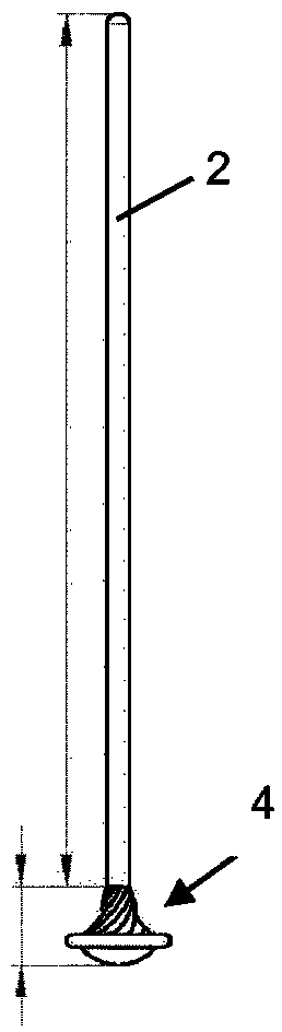
[0230] Correspondingly, figure 1 The milling cutter shown in mainly comprises a shaft part 2 with a top proximal end for being connected in a non-rotatable manner to a known driving device and a complex milling head 4 at the front distal end, the milling head having complex geometry.

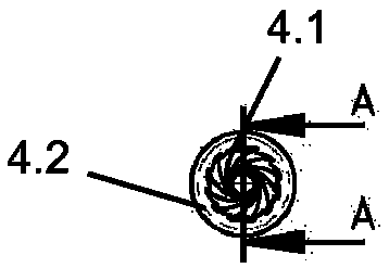
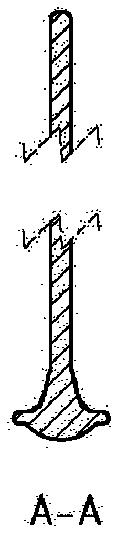
[0231] The milling head 4 comprises a proximally oriented or proximally operated sharp milling surface 4.1 (here with a tooth structure), which widens from the outer peripheral surface of the shaft part 2 towards the distal end to a maximum circumference, wherein a protective ring 4.2 Surrounding the maximum perimeter in a ring configuration and projecting radially outwardly beyond the maximum perimeter. A distal protruding protective cap 4.3 is provided at the distal front end with a somewhat reduced radius, and the protective cap 4.3 is retracted or indented relative ...


PUM


Abstract

The invention relates to a surgical milling cutter which is designed to remove bone and / or cartilage tissue, comprising a shaft (2) which extends along a longitudinal axis, can rotate about same, andcan be releasably connected to a drive device and which has a proximal end that can be rotationally fixed to a drive unit and a distal end lying opposite the proximal end. A milling surface (4.1) which circumferentially surrounds the shaft (2) and extends on the distal end along the longitudinal axis of the shaft (2) is formed at the distal end, said milling surface protruding radially from the shaft and having a milling surface maximum radius R1. The aim of the invention is to prevent unwanted damage to delicate body structures. This is achieved by an atraumatic design in that a protective assembly is provided on the distal end. The protective assembly has a distal support surface and a protective assembly maximum radius R2 in order to form a protective ring (4.2) which surrounds the milling surface maximum radius R1 in a circular manner.

Description

technical field [0001] The present invention relates to a surgical mill designed for the removal of bone and / or cartilage tissue, said surgical mill comprising a shaft defining a longitudinal axis and rotatable about an axis of rotation and having a nominal diameter, non-opposite A proximal end rotatably connected to the drive unit and a distal end opposite the proximal end, wherein a milling head is provided at the distal end, the milling head has a milling surface that surrounds the shaft circumferentially and along the shaft , wherein the milled surface is defined by a proximally located milled surface proximal end and a distally located milled surface distal end and a milled surface maximum radius. The terms proximal and distal are to be interpreted with the user / surgeon of the milling tool as a point of reference. Thus, proximal means the direction in which the surgeon is located, and distal means away from the surgeon. Background technique [0002] Such an arrangemen...

Claims


Application Information

Patent Timeline
Patent Type & Authority Applications(China)
IPC IPC(8): A61B17/16
CPCA61B17/1615A61B17/1671A61B17/1679A61B17/1688A61B2017/1602A61B2090/036A61B17/1617
Inventor T·J·斯卡杰斯特
Owner SKAJSTER FAMILIENSTIFTUNG
Why Eureka
Try Eureka