Method for surface machining, method for producing an engine block, device for surface machining and motor vehicle

An engine block and surface machining technology, which is applied in the fields of surface machining, manufacturing of engine blocks, devices for surface machining and motor vehicles, can solve high investment costs, high energy consumption, large operating costs, etc. problems, to achieve the effect of saving operating costs, improving efficiency, and reducing energy consumption

Active Publication Date: 2019-03-15
VOLKSWAGEN AG
View PDF9 Cites 3 Cited by
  • Summary
  • Abstract
  • Description
  • Claims
  • Application Information

AI Technical Summary

Problems solved by technology

[0004] In known methods, suction produces very large air flows with consequently large vacuum sources and thus high investment costs
In addition, the energy consumption is high, which entails high operating costs
Likewise, the equipment needed to clean the air flow should be dimensioned accordingly

Method used


Image

  • Method for surface machining, method for producing an engine block, device for surface machining and motor vehicle
  • Method for surface machining, method for producing an engine block, device for surface machining and motor vehicle
  • Method for surface machining, method for producing an engine block, device for surface machining and motor vehicle

Examples


Embodiment Construction

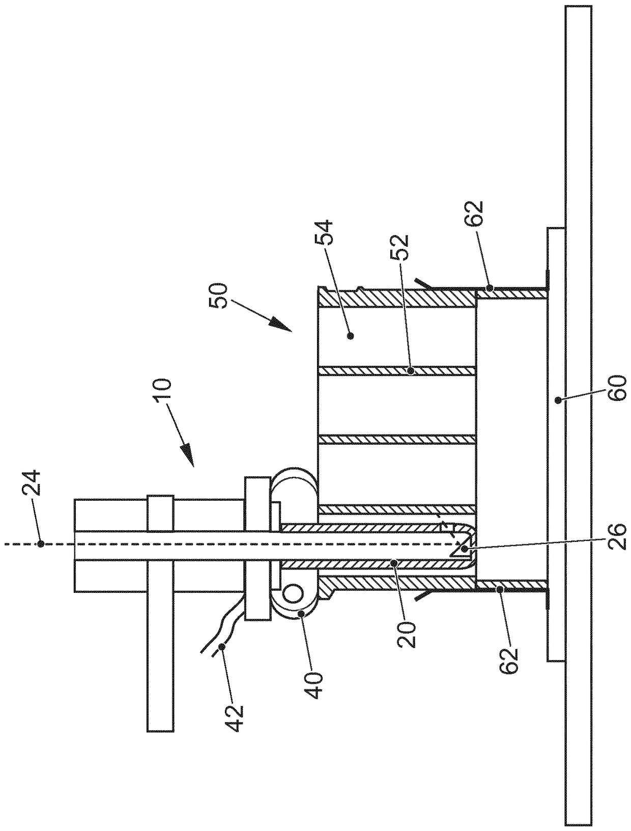
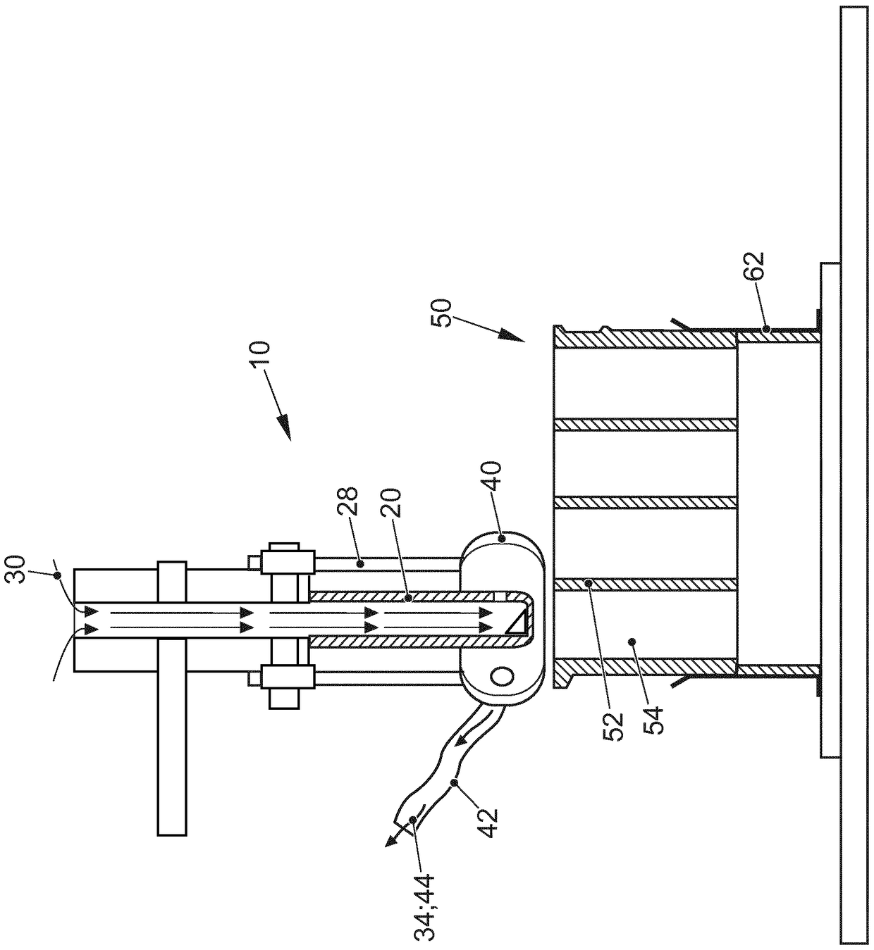
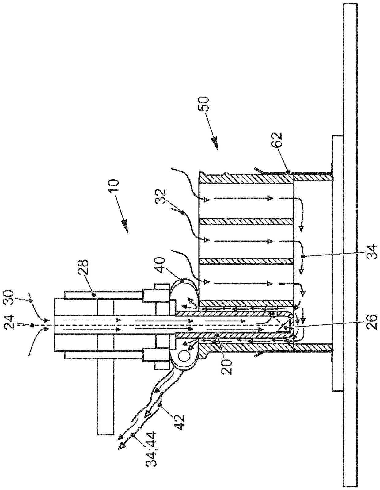
[0061] figure 1 A section through a device 10 for surface machining according to the invention is shown. It includes a machining tool 20 , also called an inner machining head, which is embodied in the form of a hollow rod. The machining tool 20 can be guided vertically by means of a guide device 28 in order to facilitate its introduction into a hollow cavity, for example a cylinder 54 of an engine block. A purge gas flow aligned along the longitudinal axis of the machining tool 20 and extending from top to bottom in the direction of the side of the machining tool 20 that can be driven into the cylinder takes place in the interior of the machining tool 20 . Arranged at the lower end of the processing tool 20 is a reflector 26 , also referred to as a deflection prism, which is suitable for reflecting the laser beam, which is also guided from above through the processing tool 20 , and directing it via the outlet to the cylinder 54 The piston travels at the surface of the track ...


PUM


Abstract

The invention relates to a method for machining the surface of a cavity, particularly a piston track of a cylinder of an internal combustion engine block (50), according to which the cavity is provided, a machining tool (20) is inserted into the cavity, and the surface of the cavity is machined using the machining tool (20). Furthermore, a flushing gas (30) is introduced into the cavity and a suction system is connected to an opening in the cavity in order to suck out flushing gas (30) and particles that may have been produced during the machining.

Description

technical field [0001] The invention relates to a method for surface machining of hollow cavities, in particular cylinders of an internal combustion engine block (Verbrennungsmotorblock, sometimes also called an internal combustion engine block), a piston travel path (Kolbenlaufbahn), a motor block ( Motorblock), a device for surface machining of hollow cavities and a motor vehicle, especially a passenger car. Background technique [0002] In the case of manufacturing the piston travel paths of the cylinders in the engine block of an internal combustion engine, the piston travel paths are typically structured. This can be carried out as a preparatory step for thermal cladding. An ablation method with laser radiation, for example, can be used as a method for structuring the surface. [0003] In the case of ablation methods for surface processing, the ablated material is typically accumulated as solid particles, liquid droplets or gaseously or as a vapor. It should be remov...

Claims


Application Information

Patent Timeline
Patent Type & Authority Applications(China)
IPC IPC(8): B23K10/02B23K101/00B23K26/342B23K26/142B23K26/352B23K9/04B23K26/10
CPCB23K9/04B23K10/027B23K26/106B23K26/342B23K26/142B23K26/352B23K2101/006
Inventor P.M.米勒K.S.克利梅克M.希尔施费尔特S.里希特
Owner VOLKSWAGEN AG
Why Eureka
Try Eureka