
Rail disassembling device

A technology for rails and conveying rails, applied in the field of rail disintegrating devices, can solve the problems of high labor intensity, time-consuming and laborious manual sorting, and waste of profiles, and achieve the effects of being beneficial to maintenance, reducing noise, and improving labor efficiency.

Pending Publication Date: 2019-03-19
TIANJIN DAQIANG STEEL
View PDF7 Cites 0 Cited by
  • Summary
  • Abstract
  • Description
  • Claims
  • Application Information

AI Technical Summary

Problems solved by technology

[0003] At present, in the process of rail recycling and reuse, the rails need to be cracked and processed into shaped materials for reprocessing. When processing shaped materials, the rails are I-shaped, including long vertical boards, short vertical boards and horizontal boards, which are first processed with a plasma cutting machine. Thermal cutting, draw a line at the joint between the long vertical plate and the horizontal plate to form a cutting mark, then place the divided rail on the air hammer, use the punching force to punch, first complete the punching of the long vertical plate and the horizontal plate Then, under the action of strong impact force and height difference, the short vertical plate and horizontal plate are punched off. One rail is divided into three steel plate profiles, and then reused. Due to the heavy number of rails, each time the air hammer The materials are all manually operated, which is time-consuming and labor-intensive, and the strength is high, and the length of each time is relatively short, within 2 meters. Whether it is the limitation of the working area of ​​the air hammer or the limitation of the labor intensity of the operator, it cannot be directly hammered. Longer scrap rails lead to inefficiency, and the shorter steel profiles will form many interfaces during the reuse process. The interfaces will be cut and docked, which will cause a waste of profiles. After the rails are broken, different The specifications are classified according to categories, manual classification is labor-intensive and inefficient

Method used


Image

  • Rail disassembling device
  • Rail disassembling device
  • Rail disassembling device

Examples


Embodiment Construction

[0045] In order to make the above objects, features and advantages of the present invention more comprehensible, specific implementations of the present invention will be described in detail below in conjunction with the accompanying drawings.

[0046] In the following description, a lot of specific details are set forth in order to fully understand the present invention, but the present invention can also be implemented in other ways different from those described here, and those skilled in the art can do it without departing from the meaning of the present invention. By analogy, the present invention is therefore not limited to the specific examples disclosed below.

[0047] Secondly, the present invention is described in detail in combination with schematic diagrams. When describing the embodiments of the present invention in detail, for the convenience of explanation, the cross-sectional view showing the device structure will not be partially enlarged according to the gener...


PUM


Abstract

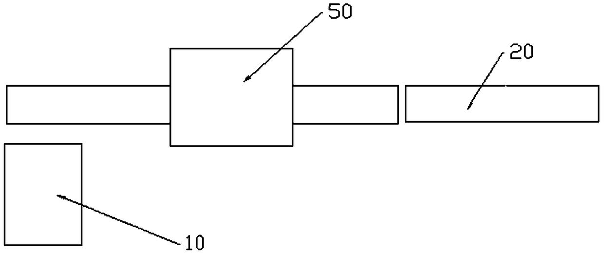
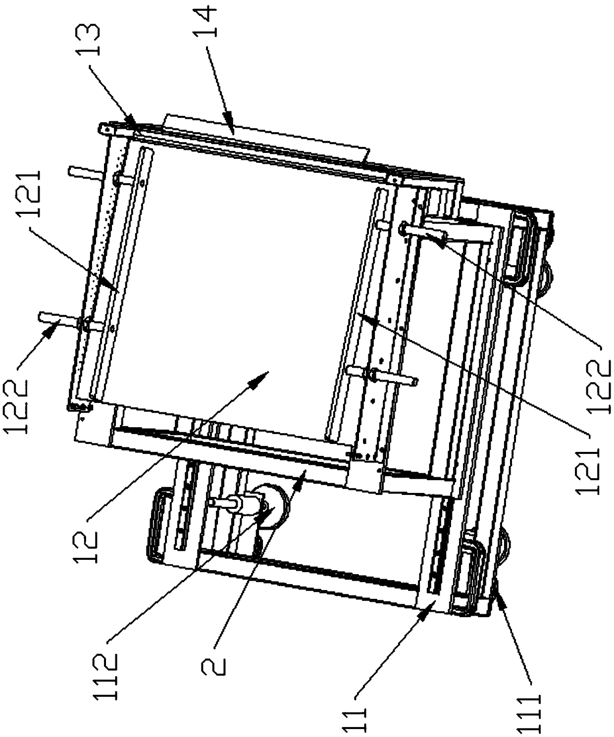
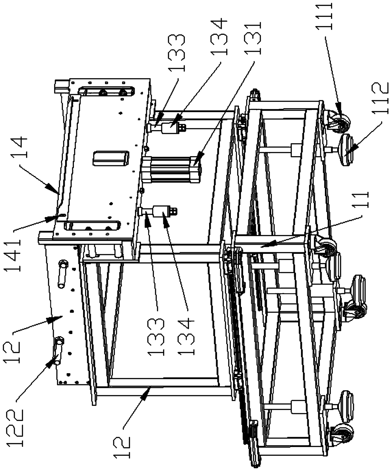
The invention discloses a rail disassembling device and belongs to the field of steel machining equipment. The rail disassembling device comprises a feed component, a hammer-pressing component and a discharging component which are connected in sequence; the hammer-pressing component comprises a conveying track, a hammer-pressing plate, a hammer-pressing cylinder, a hammer-pressing box body and a crosser; the conveying track is arranged in a manner of penetrating through the hammer-pressing box body; the hammer-pressing cylinder is arranged at the two ends of the lower end face of the hammer-pressing plate; the hammer-pressing plate is fixedly connected with a force applying shaft of the hammer-pressing cylinder; one end, far away from the hammer-pressing plate, of the hammer-pressing cylinder is fixedly arranged on the bottom surface; the longitudinal center line of the hammer-pressing plate is arranged in parallel with that of the conveying track; the crosser is arranged at the internal top end of the hammer-pressing box body; the crosser and the hammer-pressing plate are arranged in a manner of corresponding to each other in the vertical direction; the conveying track is providedwith a plurality of rotating wheels; the rotating wheels are driven to rotate by the same motor and chain mechanism; each rotating wheel is provided with a positioning groove; and each positioning groove is arranged corresponding to a third profile of the rail. The rail disassembling device disclosed by the invention can realize automatic feeding, fracturing and discharging of the rail and is high in automation degree, high in work efficiency and low in labor intensity.

Description

technical field [0001] The invention belongs to the field of steel processing equipment and relates to the reprocessing of waste rails, in particular to a rail decomposition device. Background technique [0002] The rails are used on the railway and cooperate with the switch, so that the train can walk without turning. With the rapid development of the economy, the laying distance of the rails is getting longer and longer, and the high-speed rail is also developing rapidly, but China needs a lot of rails. The high-speed rail runs abroad, and the demand for the number of rails is greater. In the past, the old rails could not meet the passage of high-speed trains. Therefore, the rails need to be replaced, and the old rails can be recycled and reused. [0003] At present, in the process of rail recycling and reuse, the rails need to be cracked and processed into shaped materials for reprocessing. When processing shaped materials, the rails are I-shaped, including long vertical ...

Claims


Application Information

Patent Timeline
Patent Type & Authority Applications(China)
IPC IPC(8): B09B3/00
CPCB09B3/00
Inventor 赵秀永
Owner TIANJIN DAQIANG STEEL
Learn More