A method for manufacturing a bimetal composite pipe end treatment structure
A bimetallic composite pipe and end treatment technology, which is applied in the direction of manufacturing tools, metal processing equipment, welding equipment, etc., can solve the problems of low pass rate of corrosion resistance performance flaw detection, etc., to solve poor welding quality, avoid air hole defects and The effects of non-fusion defects and avoidance of damage to corrosion resistance
- Summary
- Abstract
- Description
- Claims
- Application Information
AI Technical Summary
Problems solved by technology
Method used
Image

Examples
Embodiment 1
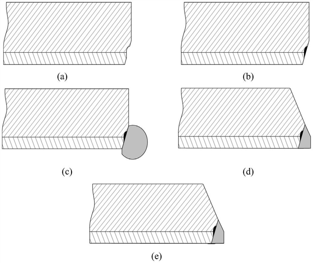
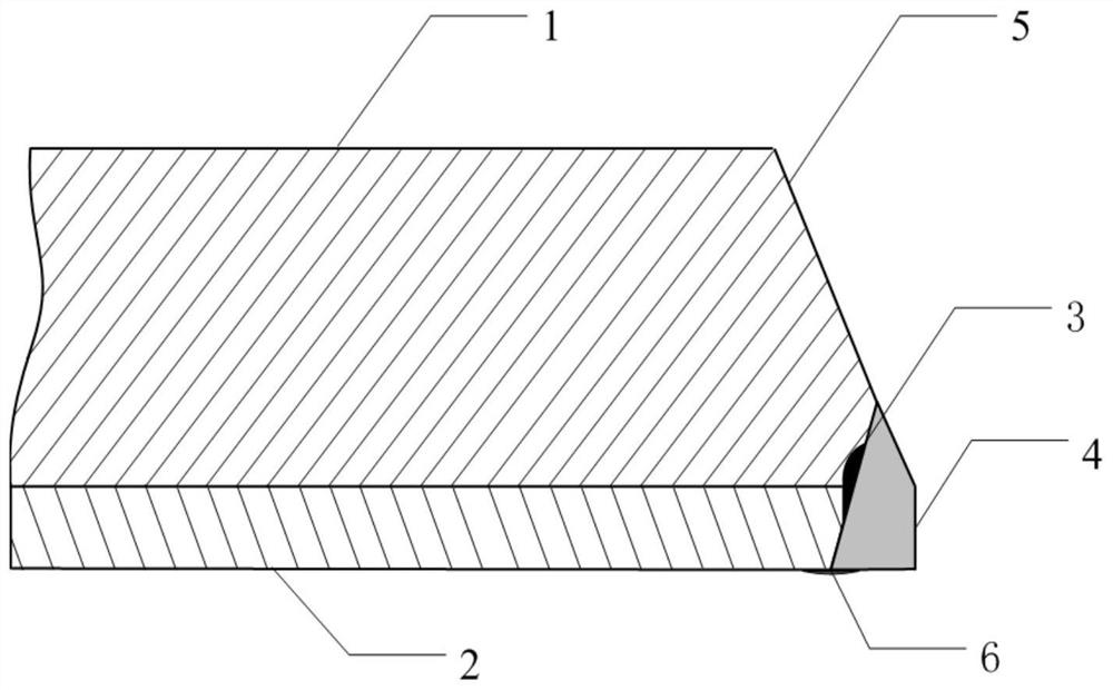
[0031] See attached figure 1 And attached figure 2 As shown, taking the 316L / L245 composite pipe composed of 316L stainless steel liner and L245 base pipe with a specification of 89×(7+2)mm as an example, the pipe end treatment structure and method of the present invention include the following steps :
[0032] 1) Processing of the first groove surface: use machining methods to process the inner groove at the pipe end with an angle of 35°, the groove height is 6.0mm, and process half of the reverse U-shaped groove at the junction of the carbon steel and the liner along the groove surface. The U-shaped transition zone adopts a semicircular transition, starting from the interface between carbon steel and liner and ending at the beveled carbon steel base pipe surface, with a radius of 2.5mm. The U-shaped upright end starts at the interface between carbon steel and liner and ends at Groove liner surface, height is 1.0mm, see figure 1 a);
[0033] 2) Semi-reverse U-shaped groo...
Embodiment 2
[0039] See attached figure 1 And attached figure 2 As shown, taking the 904L / L360 composite pipe formed by the 904L stainless steel liner and the L360 base pipe, the specification is 76×(6+2)mm as an example, the pipe end treatment structure and method of the present invention include the following steps:
[0040] 1) Processing of the first groove surface: use machining methods to process an inner groove at an angle of 33° at the pipe end, with a groove height of 5.0mm, and process half of the reverse U-shaped groove at the junction of the carbon steel and the liner along the groove surface. The U-shaped transition zone adopts a semi-circular transition, starting from the carbon steel and liner interface and ending at the beveled carbon steel base pipe surface, with a radius of 2.2mm. The U-shaped upright end starts from the carbon steel and liner interface and ends at Groove liner surface, height is 0.8mm, see figure 1 a);
[0041] 2) Semi-reverse U-shaped groove sealing ...
Embodiment 3
[0047] See attached figure 1 And attached figure 2 As shown, taking the 304 / L360 composite pipe composed of 304 stainless steel liner and L360 base pipe with a specification of 89×(6+2.5)mm as an example, the pipe end treatment structure and method of the present invention include the following steps :
[0048] 1) Processing of the first groove surface: use machining methods to process an inner groove at an angle of 30° at the pipe end, with a groove height of 4.0mm, and process half of the reverse U-shaped groove at the junction of the carbon steel and the liner along the groove surface. The U-shaped transition zone adopts a semicircular transition, starting from the interface between carbon steel and liner and ending at the surface of the beveled carbon steel base pipe, with a radius of 2.0mm. The U-shaped upright end starts at the interface between carbon steel and liner and ends at Groove liner surface, height is 0.5mm, see figure 1 a);
[0049] 2) Semi-reverse U-shap...
PUM
 Abstract
Description
Claims
Application Information
 - R&D Engineer
- R&D Manager
- IP Professional
- Industry Leading Data Capabilities
- Powerful AI technology
- Patent DNA Extraction
Browse by: Latest US Patents, China's latest patents, Technical Efficacy Thesaurus, Application Domain, Technology Topic.
© 2024 PatSnap. All rights reserved.Legal|Privacy policy|Modern Slavery Act Transparency Statement|Sitemap