Manufacturing method of bimetal composite pipe end treatment structure

A bimetal composite pipe and end treatment technology, which is applied in the direction of manufacturing tools, metal processing equipment, welding media, etc., can solve the problem of low pass rate of corrosion resistance performance flaw detection, etc., and achieve the reduction of dilution rate of corrosion resistance elements and easy control of the process , the effect of reducing the impact

Active Publication Date: 2019-03-19
BC P INC CHINA NAT PETROLEUM CORP +1
View PDF8 Cites 3 Cited by
  • Summary
  • Abstract
  • Description
  • Claims
  • Application Information

AI Technical Summary

Problems solved by technology

[0003] The purpose of the present invention is to provide a method for manufacturing the end treatment structure of a bimetallic composite pipe to overcome the shortcomings of the prior art. The present invention changes the end treatment structure by setting a semi-reverse U-shaped groove, adjusts the sealing welding process and increases the interface It can effectively avoid traditional problems such as welding defects caused by end sealing welding process, corrosion resistance reduction and low pass rate of flaw detection.

Method used


Image

  • Manufacturing method of bimetal composite pipe end treatment structure
  • Manufacturing method of bimetal composite pipe end treatment structure

Examples


Embodiment 1

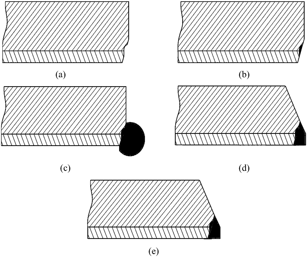
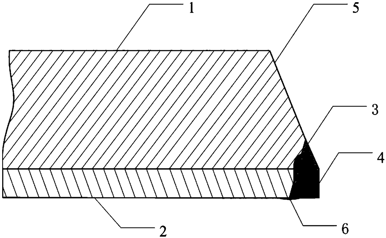
[0031] See attached figure 1 And attached figure 2 As shown, taking the 316L / L245 composite pipe composed of 316L stainless steel liner and L245 base pipe with a specification of 89×(7+2)mm as an example, the pipe end treatment structure and method of the present invention include the following steps :

[0032] 1) Processing of the first groove surface: use machining methods to process the inner groove at the pipe end with an angle of 35°, the groove height is 6.0mm, and process half of the reverse U-shaped groove at the junction of the carbon steel and the liner along the groove surface. The U-shaped transition zone adopts a semicircular transition, starting from the interface between carbon steel and liner and ending at the beveled carbon steel base pipe surface, with a radius of 2.5mm. The U-shaped upright end starts at the interface between carbon steel and liner and ends at Groove liner surface, height is 1.0mm, see figure 1 a);

[0033] 2) Semi-reverse U-shaped groo...

Embodiment 2

[0039] See attached figure 1 And attached figure 2 As shown, taking the 904L / L360 composite pipe formed by the 904L stainless steel liner and the L360 base pipe, the specification is 76×(6+2)mm as an example, the pipe end treatment structure and method of the present invention include the following steps:

[0040] 1) Processing of the first groove surface: use machining methods to process an inner groove at an angle of 33° at the pipe end, with a groove height of 5.0mm, and process half of the reverse U-shaped groove at the junction of the carbon steel and the liner along the groove surface. The U-shaped transition zone adopts a semi-circular transition, starting from the carbon steel and liner interface and ending at the beveled carbon steel base pipe surface, with a radius of 2.2mm. The U-shaped upright end starts from the carbon steel and liner interface and ends at Groove liner surface, height is 0.8mm, see figure 1 a);

[0041] 2) Semi-reverse U-shaped groove sealing ...

Embodiment 3

[0047] See attached figure 1 And attached figure 2 As shown, taking the 304 / L360 composite pipe composed of 304 stainless steel liner and L360 base pipe with a specification of 89×(6+2.5)mm as an example, the pipe end treatment structure and method of the present invention include the following steps :

[0048] 1) Processing of the first groove surface: use machining methods to process an inner groove at an angle of 30° at the pipe end, with a groove height of 4.0mm, and process half of the reverse U-shaped groove at the junction of the carbon steel and the liner along the groove surface. The U-shaped transition zone adopts a semicircular transition, starting from the interface between carbon steel and liner and ending at the surface of the beveled carbon steel base pipe, with a radius of 2.0mm. The U-shaped upright end starts at the interface between carbon steel and liner and ends at Groove liner surface, height is 0.5mm, see figure 1 a);

[0049] 2) Semi-reverse U-shap...


PUM


Abstract

The invention discloses a manufacturing method of a bimetallic composite pipe end treatment structure, and belongs to the technical field of composite material processing. The manufacturing method ofthe bimetallic composite pipe end treatment structure comprises the steps that a semi-reverse U-shaped groove is formed to change the pipe end treatment structure, so that the corrosion resistance ofa lining layer is prevented from being reduced due to dilution of corrosion-resistant elements caused by frequent heating of a lining layer, and air hole defects and incomplete fusion defects during butt welding are overcome; and welding wire components and welding processes are designed, and a welding layer on an interface cover surface is added, so that corrosion resistance continuity of liningmaterials and welding seam areas is ensured. The manufacturing method of the bimetallic composite pipe end treatment structure has simple process flow steps, the process is easy to control, industrialmechanization, automation and mass production are easy to realize, meanwhile, the welding quality is reliable, and the problems of poor welding quality, easy occurrence of welding defects, reductionof corrosion resistance and the like existing in a small-diameter composite pipe end sealing and welding method can be effectively solved.

Description

technical field [0001] The invention belongs to the technical field of composite material processing, and in particular relates to a method for manufacturing a small-caliber stainless steel-lined bimetal composite pipe end treatment structure. Background technique [0002] In recent years, ultra-deep, high-temperature, high-pressure, high-H content 2 S / CO 2 As well as elemental sulfur and other oil and gas fields appearing one after another, traditional carbon steel materials can no longer meet the needs of oil and gas field development, and the high price of corrosion-resistant alloy pipes restricts its popularization and application in oil and gas fields. An anti-corrosion pipeline for oil and gas gathering and transportation. However, the end treatment of bimetallic composite pipes is still the main factor that hinders its large-scale use, especially the problem of small-diameter composite pipes is more prominent. Since small-diameter bimetallic composite pipes cannot ...

Claims


Application Information

Patent Timeline
IPC IPC(8): B23K9/00B23K9/04B23K9/235B23K35/30B23P15/00
CPCB23K9/0026B23K9/04B23K9/235B23K35/304B23P15/00
Inventor 李发根常泽亮李为卫赵新伟李先明冯泉
Owner BC P INC CHINA NAT PETROLEUM CORP
Why Eureka
Try Eureka