Laser beam terminal pointing detection and correction method and laser processing device

A technology of laser beam and correction method, which is applied in the field of laser beam terminal pointing detection and correction, and laser processing device, can solve the problems of inability to monitor feedback correction online, and inability to guarantee the influence of laser beam, and achieve the effect of improving position accuracy

Active Publication Date: 2019-03-19
XI'AN INST OF OPTICS & FINE MECHANICS - CHINESE ACAD OF SCI
View PDF8 Cites 10 Cited by
  • Summary
  • Abstract
  • Description
  • Claims
  • Application Information

AI Technical Summary

Problems solved by technology

[0004] In order to solve the problem that offline front-end measurement cannot monitor feedback correction online and cannot guarantee the influence of external environment and sub

Method used


Image

  • Laser beam terminal pointing detection and correction method and laser processing device
  • Laser beam terminal pointing detection and correction method and laser processing device

Examples


Example Embodiment

[0033] The present invention will be further described below in conjunction with the drawings and specific embodiments.

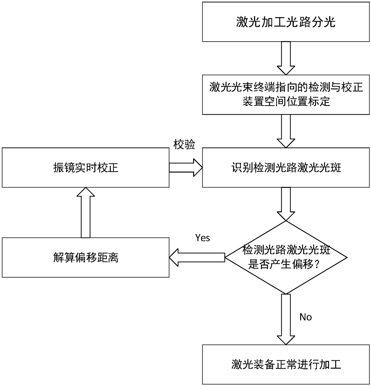
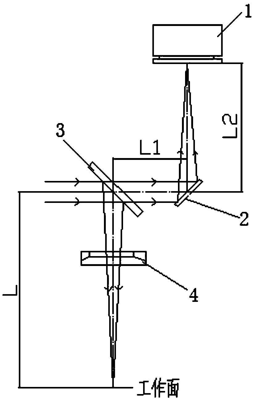
[0034] The laser beam terminal pointing detection and correction method of the present invention is used to solve the problem of laser beam pointing at the processing terminal due to long-time work of the laser equipment, deviation of the laser beam pointing, temperature drift of the galvanometer, and time drift during laser processing Offset affects the position accuracy of the processed graphics. According to the optical path conjugate principle, the spatial position of the detection and correction device of the laser beam terminal point is arranged and calibrated, so that the deviation of the spot position in the field of view is equal to the deviation of the actual laser processing spot position, which can be detected The spot position of the device represents the deviation of the spot on the laser processing surface.

[0035] From figure 1 It can be seen t...


PUM


Abstract

The invention relates to a laser beam terminal pointing detection and correction method and a laser processing device. The laser beam terminal pointing detection and correction method and the laser processing device are used for solving the problem that in the process of laser processing, because of long time operation of laser equipment, a laser beam generates pointing offset at a processing terminal caused by emitting beam pointing offset of a laser device, temperature excursion and time excursion of a galvanometric scanner and the other reasons to affect the position accuracy of a machinedfigure. According to a principle of optical path conjugation, the spatial position of a detection and correction device of laser beam terminal pointing is arranged and calibrated, the light spot position offset amount in a view field is equal to the light spot position offset amount of the actual laser processing light spot position, so that the light spot offset situation of the laser processed surface is characterized through the light spot position of the detection device; and the laser beam terminal pointing detection and correction method and the laser processing device can be widely usedin laser fine surface manufacturing, hole making, fine cutting aspects of aerospace field, automobile field, 3C field, optoelectronic field, mold field and other fields.

Description

technical field [0001] The invention belongs to the technical field of laser processing, and in particular relates to a laser beam terminal pointing detection and correction method and a laser processing device. Background technique [0002] Laser processing is an emerging special processing method and has become an inevitable choice to replace traditional manufacturing methods. Using the characteristics of the interaction between laser beams and substances, materials can be cut, welded, surface treated, drilled and micromachined. A traditional laser processing device mainly includes a laser light source for generating a laser beam and a galvanometer system for guiding the laser beam to the workpiece to be processed. The galvanometer system includes a control system and two sets of fast mirrors. In the process of processing, the instability of laser beam pointing will reduce the position accuracy of laser processing. At present, because the existing domestic equipment belon...

Claims


Application Information

Patent Timeline
IPC IPC(8): B23K26/042B23K26/064
CPCB23K26/042B23K26/064B23K26/0643
Inventor 李珣李明谭羽
Owner XI'AN INST OF OPTICS & FINE MECHANICS - CHINESE ACAD OF SCI
Why Eureka
Try Eureka