Gantry derrick allowing operation under pressure

A pressurized operation and gantry-type technology, which is applied to drilling equipment, earthwork drilling, support devices, etc., can solve the problems of high resource consumption such as manpower and material resources, no lifting capacity, and low work efficiency, so as to reduce manpower and material resources consumption, shorten workover time, and improve workover efficiency

Pending Publication Date: 2019-03-19
韩咏利
View PDF0 Cites 1 Cited by
  • Summary
  • Abstract
  • Description
  • Claims
  • Application Information

AI Technical Summary

Problems solved by technology

At present, most of the frame parts of the pressurized device only play a supporting role and do not have lifting capacity.
However, the workover under pressure will inevitably require lifting the pipe string, so this frame without lifting capacity must rely on the workover rig to work
There are two types of existing pressurized work frames with lifting capacity. One is to install a lifting cylinder on the frame. However, since the stroke of the lifting cylinder cannot be too long, the work efficiency of this frame is low. Too low, large consumption of manpower and material resources
The other is to install a single-arm mast on the frame. Due to the limitation of the mast's own load, this frame has a small lifting force and cannot be used for maintenance operations in deep wells.

Method used


Image

  • Gantry derrick allowing operation under pressure
  • Gantry derrick allowing operation under pressure
  • Gantry derrick allowing operation under pressure

Examples


Embodiment Construction

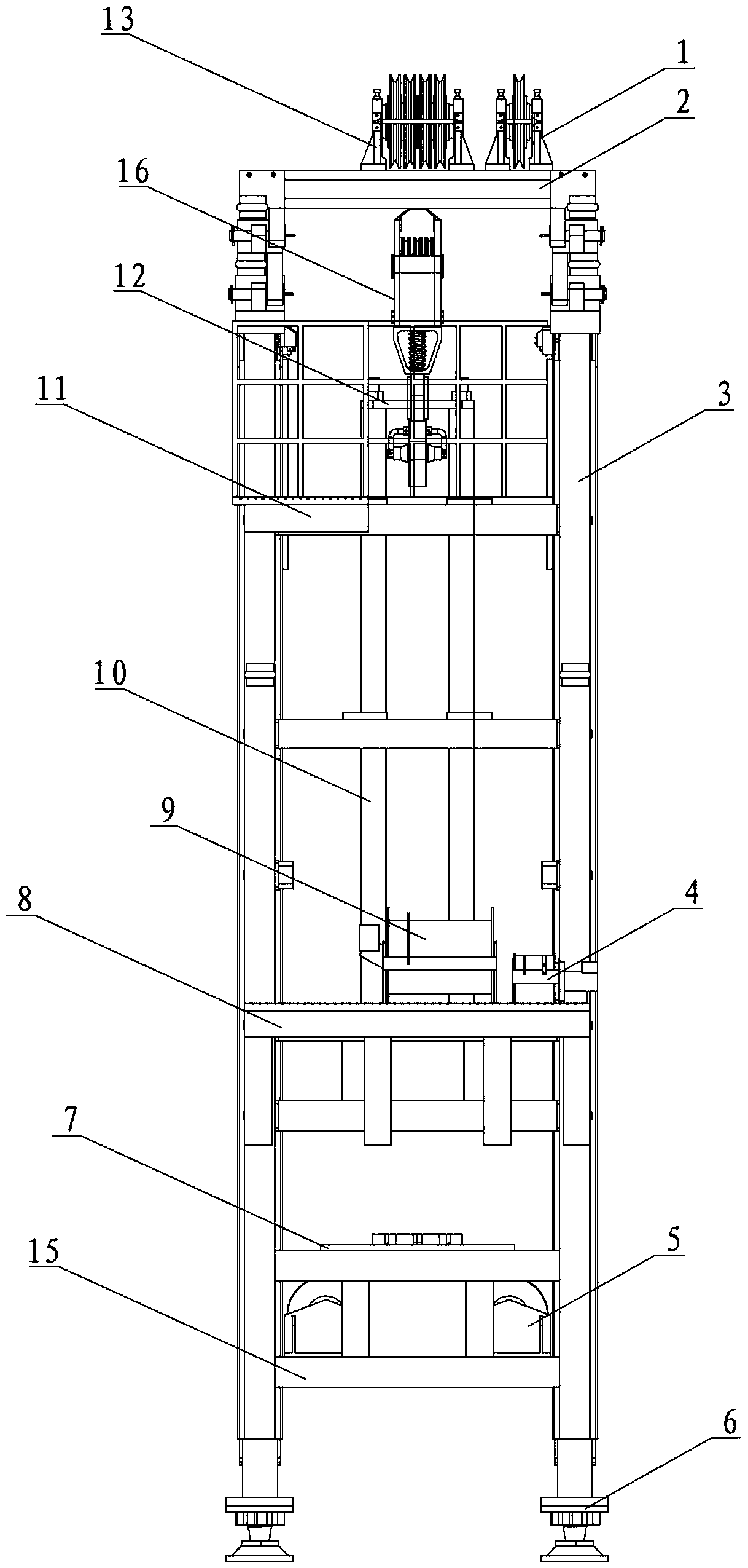
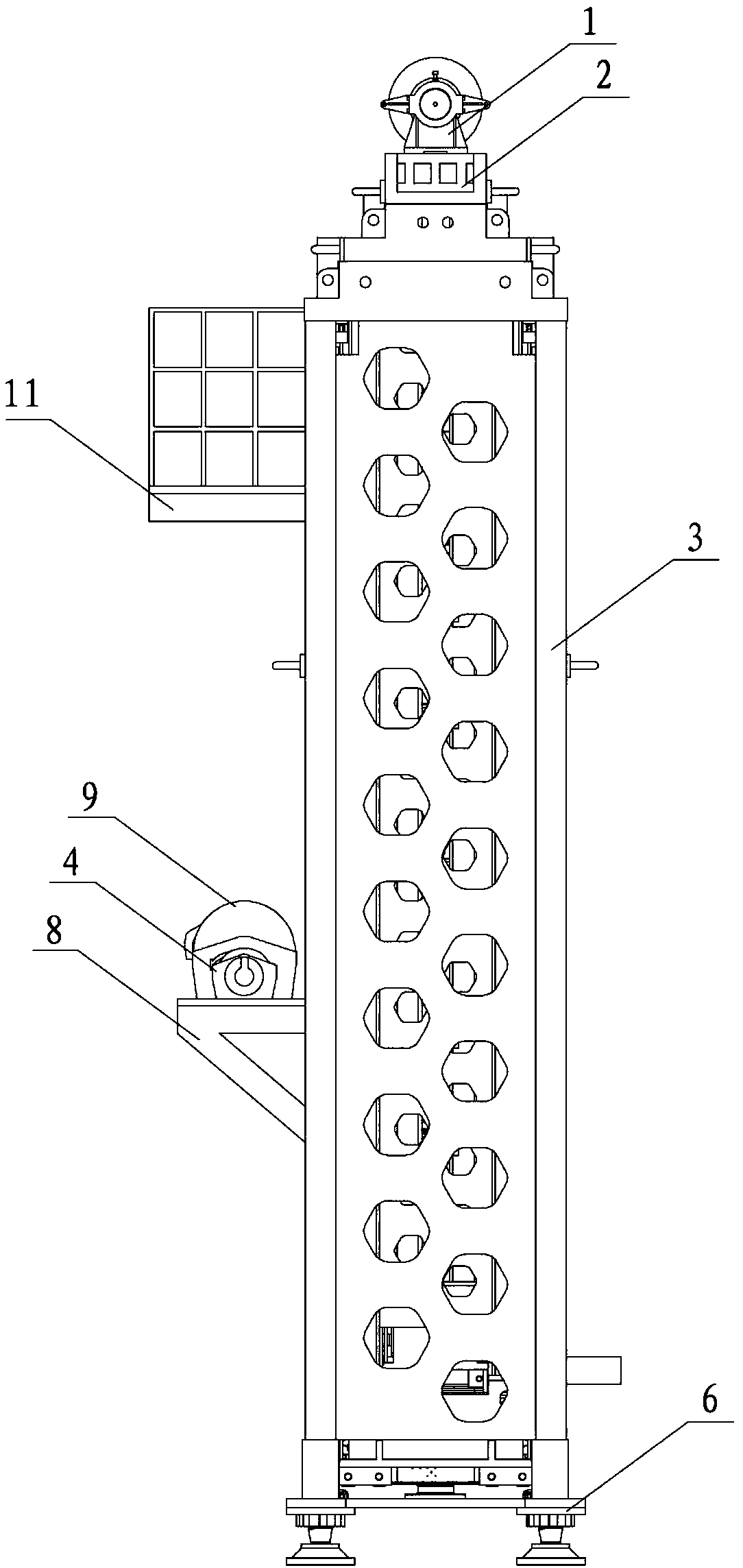
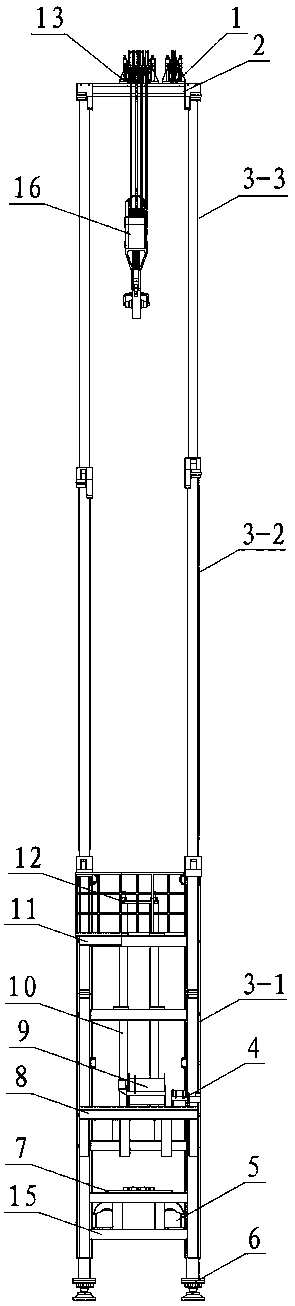
[0029] see figure 1 , figure 2 , the present invention includes two gantry masts 3, a mast beam 2, a large fixed pulley block 13, a small fixed pulley block 1, four lifting hydraulic cylinders 10, a swimming hook 16, a lifting platform 12, an operating platform 11, and a supporting platform 8 , load-bearing platform 7, large hook hydraulic winch 9, auxiliary hook hydraulic winch 4, four hydraulic legs 6 and connecting seat 15. The mast is not directly installed on the ground. There are two hydraulic outriggers on each piece of mast, and two pieces of mast have four hydraulic outriggers. These four hydraulic outriggers are placed directly on the ground to form a stable structure. If the ground is soft, a larger pad can be placed under the hydraulic outrigger.

[0030] The two ends of the mast beam 2 are respectively connected to the upper parts of the two gantry masts 3 through bolt assemblies to form a gantry type. The maximum bearing capacity of the mast beam 2 can reach 1...


PUM


Abstract

A gantry derrick allowing operation under pressure comprises two expansion masts, a mast cross beam, a walking large hook, a large fixed pulley unit, a large hook hydraulic winch and a support platform; the two expansion masts are mounted on a ground vertically through support legs; the upper ends of the two expansion masts are connected through the mast cross beam; the lower ends of the expansionmasts are fixed together through a connection seat; the large fixed pulley unit is mounted on the mast cross beam; the support platform is fixed between the two expansion masts; the large hook hydraulic winch is mounted on the support platform; a wire rope of the large hook hydraulic winch is wound around the large fixed pulley unit and connected with the walking large hook. The gantry derrick with the walking large hook has great lifting force and is convenient to operate, so that workover time is effectively shortened. The defect that existing derricks for operation under pressure have lifting force and working efficiency problems is overcome; the gantry derrick is suitable for the under-pressure workover operation for water wells, oil wells and gas wells having various depths, workoverefficiency can be improved, and consumption of manpower and material sources is reduced.

Description

technical field [0001] The invention relates to a gantry type derrick device capable of working over wells under pressure. The equipment can effectively get rid of the dependence of the under pressure equipment on the workover rig, and belongs to the technical field of petroleum. Background technique [0002] With the increase of oilfield development and the increase of single well production time, no matter for water wells, oil wells or gas wells, maintenance operations are indispensable. There are three methods of workover for pressured wells, one is to workover after decompressing, the other is to use killing fluid to kill the well and then workover, and the third is to workover under pressure. The disadvantages of depressurization and workover are that the time for depressurization and recovery of production in the later period is longer, and the maintenance efficiency is low; there are two main disadvantages of maintenance with killing hydraulic wells. One is that the k...

Claims


Application Information

Patent Timeline
Patent Type & Authority Applications(China)
IPC IPC(8): E21B15/00E21B19/00
CPCE21B15/00E21B19/00
Inventor 韩咏利
Owner 韩咏利
Why Eureka
Try Eureka