Oil production device and method for controlling pressure of oil layer through double-layer oil pipe

It is a technology for oil layer pressure and oil production equipment, which is applied in the direction of drilling pipe, casing, and production fluid, etc. It can solve the problems of affecting liquid production, degassing of crude oil in the upper oil layer, and large pressure difference in the upper oil layer, so as to improve operation reliability, Improve the stress condition and reduce the effect of pressure interference

Active Publication Date: 2019-03-19
PETROCHINA CO LTD +1
View PDF11 Cites 0 Cited by
  • Summary
  • Abstract
  • Description
  • Claims
  • Application Information

AI Technical Summary

Problems solved by technology

[0002] For some oilfields, oil wells span a large span (300-850m), and if the general oil production method is adopted, the pressure requirement of only one oil layer can be met, that is, if the pressure of the upper oil layer is satisfied, the pressure difference of the lower oil layer (the pressure of the oil layer and the pressure of the liquid column on the oil layer If the pressure of the lower oil layer is satisfied, the pressure difference of the upper oil layer is too large, which may cause a large amount of degassing of the crude oil in the upper oil layer, resulting in gas cones and affecting the liquid production.
In recent years, some layered oil production methods have been put into field use, but they are only suitable for the production of oil wells with a span of less than 300m. For this reason, a kind of oil production device and method for controlling the pressure of oil layers with double-layer oil pipes has been developed. Pressure control to ensure that each oil layer is produced under a reasonable pressure, give full play to the production capacity of the oil layer, realize layered oil recovery, and increase the liquid production rate of a single well

Method used


Image

  • Oil production device and method for controlling pressure of oil layer through double-layer oil pipe

Examples


specific Embodiment approach

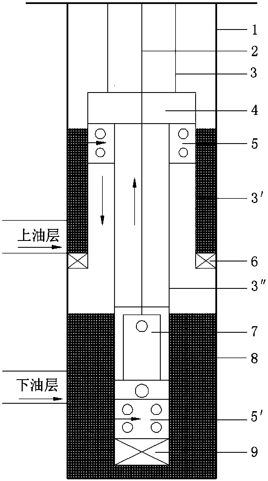
[0017] Specific embodiments: The present invention will be further described below in conjunction with the accompanying drawings: a kind of oil production device for controlling the oil layer pressure with double-layer oil pipes consists of casing 1, sucker rod 2, oil pipe one 3, oil pipe buckle 4, screen pipe one 5, oil pipe Two 3', slip packer 6, tubing three 3", plunger 7, pump barrel 8, screen tube two 5', and plug 9; the upper end of tubing buckle 4 in casing 1 is connected with tubing one 3 screw connections, the lower end of tubing change button 4 is connected with screen tube 1 5 with screws, screen tube 1 5 is connected with tubing 2 3′, and slip packer 6 in sequence, and tubing 3 3″ is connected with pump barrel 8, The screen tube 2 5' and the plug 9 are connected with screws in turn, and the plunger 7 is connected with the sucker rod 2 with screws.

[0018] The oil production method of an oil production device using a double-layer oil pipe to control the pressure of...


PUM


Abstract

The invention relates to the technical field of oil production engineering, and belongs to an oil production device and method for controlling the pressure of oil layers through a double-layer oil pipe. The device and method solve the problem about pressure interference between the large-span oil layers (300-850 m). The device comprises a casing pipe (1), an oil pumping rod (2), a first oil pipe (3), an oil pipe adapter (4), a first screen pipe (5), a second oil pipe (3'), a slip type packer (6), a third oil pipe (3''), a plunger (7), a pump cylinder (8), a second screen pipe (5') and a pipe plug (9). An annular space is formed by the casing pipe (1) and the second oil pipe (3'), a fluid on the upper oil layer enters a well through the annular space and the first screen pipe (5), the fluidin the annular space applies certain pressure on the upper oil layer, and it is guaranteed that the upper oil layer conducts production in a reasonable pressure range. The device has the advantages of adjusting the pressure interference between the oil layers, suitable for oil wells capable of outputting sand on the upper layer and producing a lot of gas on the lower layer and the like.

Description

technical field [0001] The invention relates to the technical field of oil production engineering, and belongs to an oil production device and method for controlling the pressure of an oil layer by a double-layer oil pipe. Background technique [0002] For some oilfields, oil wells span a large span (300-850m), and if a general oil production method is adopted, it can only meet the pressure requirements of one oil layer, that is, if the pressure of the upper oil layer is met, the pressure difference of the lower oil layer (the pressure of the oil layer and the pressure of the liquid column on the oil layer If the pressure difference of the upper oil layer is too large if the pressure of the lower oil layer is satisfied, it may cause a large amount of degassing of crude oil in the upper oil layer, resulting in gas cones and affecting the liquid production. In recent years, some layered oil recovery methods have been put into field use, but they are only suitable for the produ...

Claims


Application Information

Patent Timeline
Patent Type & Authority Applications(China)
IPC IPC(8): E21B43/12E21B17/00E21B43/08
CPCE21B17/00E21B43/086E21B43/12
Inventor 魏纪德于波郑国兴李巍巍赵云龙宋阳
Owner PETROCHINA CO LTD
Why Eureka
Try Eureka