Oil-saving and emission-reducing system of engine

A technology for engines and exhaust valves, applied in engine components, engine control, machines/engines, etc., can solve the problems of large starting work, effort, starter and battery damage, etc., and achieve the effect of reducing fuel consumption

Inactive Publication Date: 2019-03-19
陈朝鹏
View PDF8 Cites 0 Cited by
  • Summary
  • Abstract
  • Description
  • Claims
  • Application Information

AI Technical Summary

Problems solved by technology

The existing automobile engine has not been equipped with a corresponding decompression mechanism for a long time, resulting in a large degree of carbon deposits in the engine and a certain degree of backflow of lubricating oil, the decline in lubrication effect causes more wear, self-starting and stopping in a short period of time, untimely Self-starting will damage the starter and battery; in addition, this type of engine is not equipped with a decompression mechanism. Due to the pressure in the combustion chamber when the engine stops, the crankshaft rotation torque required for the next start is relatively large, and the starting work is large. strenuous

Method used


Image

  • Oil-saving and emission-reducing system of engine
  • Oil-saving and emission-reducing system of engine

Examples


Embodiment 1

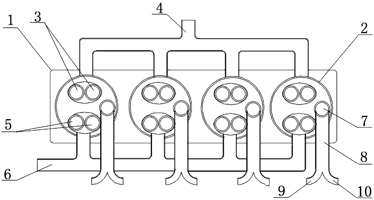
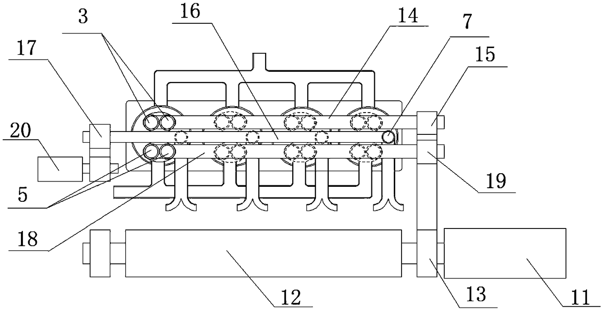
[0017] Such as figure 1 As shown, the present invention includes an engine 1, and several combustion chambers 2 located on the engine 1, each combustion chamber 2 includes two intake valves 3 and two exhaust valves 5, and also includes a decompression mechanism. The decompression mechanism includes a decompression valve 7, a decompression camshaft 16, a decompression runner 17 and a servo motor 20. The decompression valve 7 is arranged on each combustion chamber 2, and a decompression camshaft is arranged directly above the decompression door 7. 16. The decompression runner 17 at the end of the decompression camshaft 16 is connected to the servo motor 20; the decompression valve 7 is connected to the decompression pipe 8, and the end of the decompression pipe 8 is divided into two, which are divided into the intake branch pipe 9 and the exhaust pipe. Air branch pipe 10, wherein the intake branch pipe 9 is connected with the intake pipe 4 of the intake valve 3, and the exhaust ...

Embodiment 2

[0030] Such as figure 1 and figure 2 In the embodiment of the present invention given, the decompression pipe 8 is connected with the intake pipe 4 and the exhaust pipe 6 respectively, and the layout of the intake pipe 4 and the exhaust pipe 6 is selected according to actual needs, and is not limited to the main pipe of the intake pipe 4. The merging position of the exhaust pipe 6 is arranged in the middle of all the intake pipes 4, and the merging position of the main pipe of the exhaust pipe 6 is not limited to being arranged on the left side of all the exhaust pipes 6.

[0031] Similarly, the intake runner 15 at the end of the intake camshaft 14, the exhaust runner 19 at the end of the exhaust camshaft 18, the decompression runner 17 at the end of the decompression camshaft 16, and the decompression runner 17 at the end of the crank wheel The crank wheel 13 is not limited to being arranged on the right side of the combustion chamber 2, and can also be selected on the left...

Embodiment 3

[0035] The present invention can cooperate with the sensor to constitute the control system for fuel saving and emission reduction of the engine 1 .

[0036] When the cylinder deactivation system is working, the cylinder pressure information in the combustion chamber 2 of the engine 1 is collected through the mass-produced piezoresistive cylinder pressure sensor arranged in the cylinder, and the crankshaft 12 of the engine 1 is determined according to the cylinder pressure information in the combustion chamber 2 of the engine 1 phase information, and then determine the speed information of the engine 1 according to the phase information of the crankshaft 12 of the engine 1; finally, the controller of the engine 1 judges and drives the injector according to the phase information and speed information of the engine 1. When it is detected that the rotational speed information of the transmitter exceeds 800r / min, the crankshaft motor 11 driving the crankshaft 12 does not intervene ...


PUM


Abstract

The invention relates to an oil-saving and emission-reducing system of an engine and belongs to the technical field of energy saving and emission reducing. The oil-saving and emission-reducing systemof the engine comprises the engine and a plurality of combustors located in the engine. Each combustor comprises two air inlet doors and two air outlet doors. The oil-saving and emission-reducing system further comprises a pressure reducing mechanism. The pressure reducing mechanism comprises pressure reducing doors, a pressure reducing camshaft, a pressure reducing rotating wheel and a servo motor. The pressure reducing doors are arranged on the combustors. The pressure reducing camshaft is arranged over the pressure reducing doors. The pressure reducing rotating wheel at the end of the pressure reducing camshaft is connected with the servo motor. The pressure reducing doors are connected with a pressure reducing pipe, the tail end of the pressure reducing pipe is divided into two parts including an air inlet branch pipe and an air outlet branch pipe, the air inlet branch pipe is connected with air inlet pipes of the air inlet doors, and the air outlet branch pipe is connected with air outlet pipes of the air outlet doors. According to the oil-saving and emission-reducing system of the engine, due to the fact that the pressure reducing mechanism is additionally arranged, the problems that the lubricating effect is lowered during engine off, the crankshaft torque is large and running is unsmooth during starting are solved, and power consumption and oil consumption of an automobile combustor are reduced.

Description

technical field [0001] The invention relates to an engine fuel saving and emission reduction system, which belongs to the technical field of energy saving and emission reduction. Background technique [0002] In the prior art, four combustion chambers are arranged on the automobile engine, and each combustion chamber includes two intake valves and two exhaust valves, and the camshaft arranged directly above the intake valves can control the opening of the intake valves. and off. The existing automobile engine has not been equipped with a corresponding decompression mechanism for a long time, resulting in a large degree of carbon deposits in the engine and a certain degree of backflow of lubricating oil, and the decline in lubrication effect causes more wear, self-starting and stopping in a short period of time, untimely Self-starting will damage the starter and battery; in addition, this type of engine is not equipped with a decompression mechanism. Due to the pressure in t...

Claims


Application Information

Patent Timeline
IPC IPC(8): F01L13/08F01L9/04F02D13/00F01L9/22
CPCF01L13/08F02D13/00F01L9/20
Inventor 陈朝鹏
Owner 陈朝鹏
Why Eureka
Try Eureka