Orbiting scroll and scroll compressor
A scroll compressor and moving scroll technology, applied in the field of compressors, can solve problems such as collision and friction, and achieve the effects of reducing friction, occupying less space, and eliminating processing and material extrusion processes.
- Summary
- Abstract
- Description
- Claims
- Application Information
AI Technical Summary
Problems solved by technology
Method used
Image
Examples
Embodiment 1
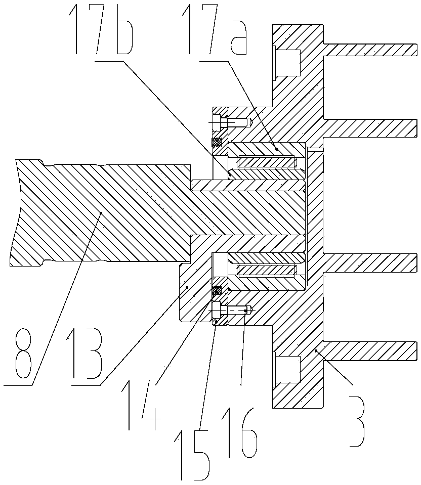
[0042] Such as Figures 1 to 3 As shown, the present invention provides a movable scroll 3,
[0043] The back of the movable scroll 3 is provided with an annular bearing protrusion coaxial therewith, and the inner cavity of the bearing protrusion constitutes a bearing hole;
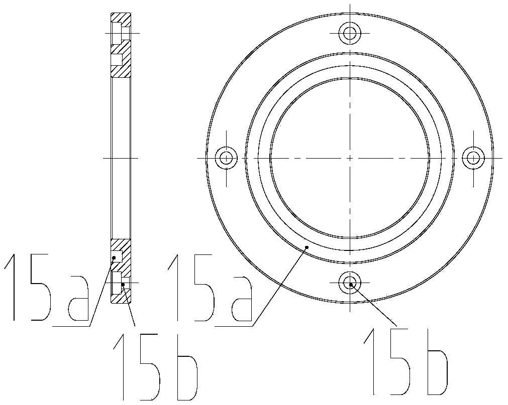
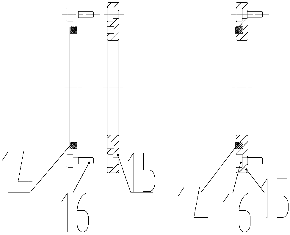
[0044] The outer end surface of the bearing protrusion is provided with a limiting member 15; the outer end surface of the limiting member 15 is provided with a wear-resistant member.
[0045] The limit piece 15 arranged on the outer end surface of the bearing protrusion can axially limit the radial bearing 17 when the bearing protrusion is thermally deformed or subjected to uneven force, and the complicated processing and material extrusion process are omitted The wear-resistant parts arranged on the outer end surface of the limiter 15 can effectively avoid the direct collision with the bearing protrusion when the eccentric sleeve 13 moves up, greatly reducing the friction between the eccentric sleeve 1...
Embodiment 2
[0052] Such as Figure 4 with Figure 5 As shown, the difference between this embodiment and Embodiment 1 is that the limiting member 15 is fixedly connected to the bearing hole through interference fit; specifically:
[0053] One end of the limiter 15 is provided with an annular first protrusion whose outer diameter is equal to the outer diameter of the limiter 15 and whose inner diameter is smaller than the inner diameter of the limiter 15. The outer end surface of the bearing protrusion is provided with an inner diameter equal to The inner diameter and outer diameter of the bearing hole are smaller than the outer diameter of the bearing hole, and the ring-shaped second protrusion has an interference fit between the inner wall surface of the first protrusion and the outer wall surface of the second protrusion to realize the position limiting Part 15 is fixedly connected with the outer end surface of the bearing protrusion;
[0054] The height of the first protrusion is les...
Embodiment 3
[0056] Such as Image 6 with Figure 7 As shown, the difference between this embodiment and Embodiment 1 is that the limiting member 15 is fixedly connected to the bearing hole through interference fit; specifically:
[0057] Further, one end of the limiting member 15 is provided with an annular third protrusion whose inner diameter is equal to the inner diameter of the limiting member 15 and whose outer diameter is smaller than the outer diameter of the limiting member 15, and the outer end surface of the bearing protrusion is provided with There is an annular fourth protrusion whose outer diameter is equal to the outer diameter of the bearing hole and whose inner diameter is smaller than the inner diameter of the bearing hole. The outer wall surface of the third protrusion and the inner wall surface of the fourth protrusion are interference fit to realize the The fixed connection between the limiting member 15 and the outer end surface of the bearing protrusion;
[0058] T...
PUM
 Abstract
Description
Claims
Application Information
 - R&D
- Intellectual Property
- Life Sciences
- Materials
- Tech Scout
- Unparalleled Data Quality
- Higher Quality Content
- 60% Fewer Hallucinations
Browse by: Latest US Patents, China's latest patents, Technical Efficacy Thesaurus, Application Domain, Technology Topic, Popular Technical Reports.
© 2025 PatSnap. All rights reserved.Legal|Privacy policy|Modern Slavery Act Transparency Statement|Sitemap|About US| Contact US: help@patsnap.com


