
Reversing valve and rotating valve core thereof

A technology of rotating spool and reversing valve, applied in valve details, multi-way valves, valve devices, etc., can solve the problem of many components, achieve low production cost, ensure fit, and increase sealing performance

Pending Publication Date: 2019-03-19
刘小祥
View PDF0 Cites 2 Cited by
  • Summary
  • Abstract
  • Description
  • Claims
  • Application Information

AI Technical Summary

Problems solved by technology

[0004] Aiming at the problem that multiple solenoid valves and many components are used to control multiple directional valves and tangential valves, the present invention provides a directional valve and its rotary valve core

Method used


Image

  • Reversing valve and rotating valve core thereof
  • Reversing valve and rotating valve core thereof
  • Reversing valve and rotating valve core thereof

Examples


Embodiment 1

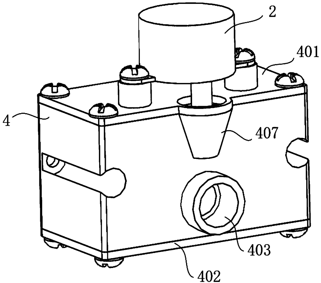
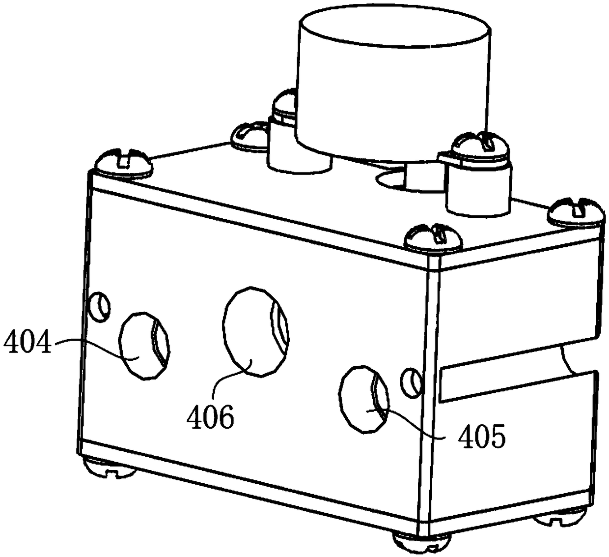
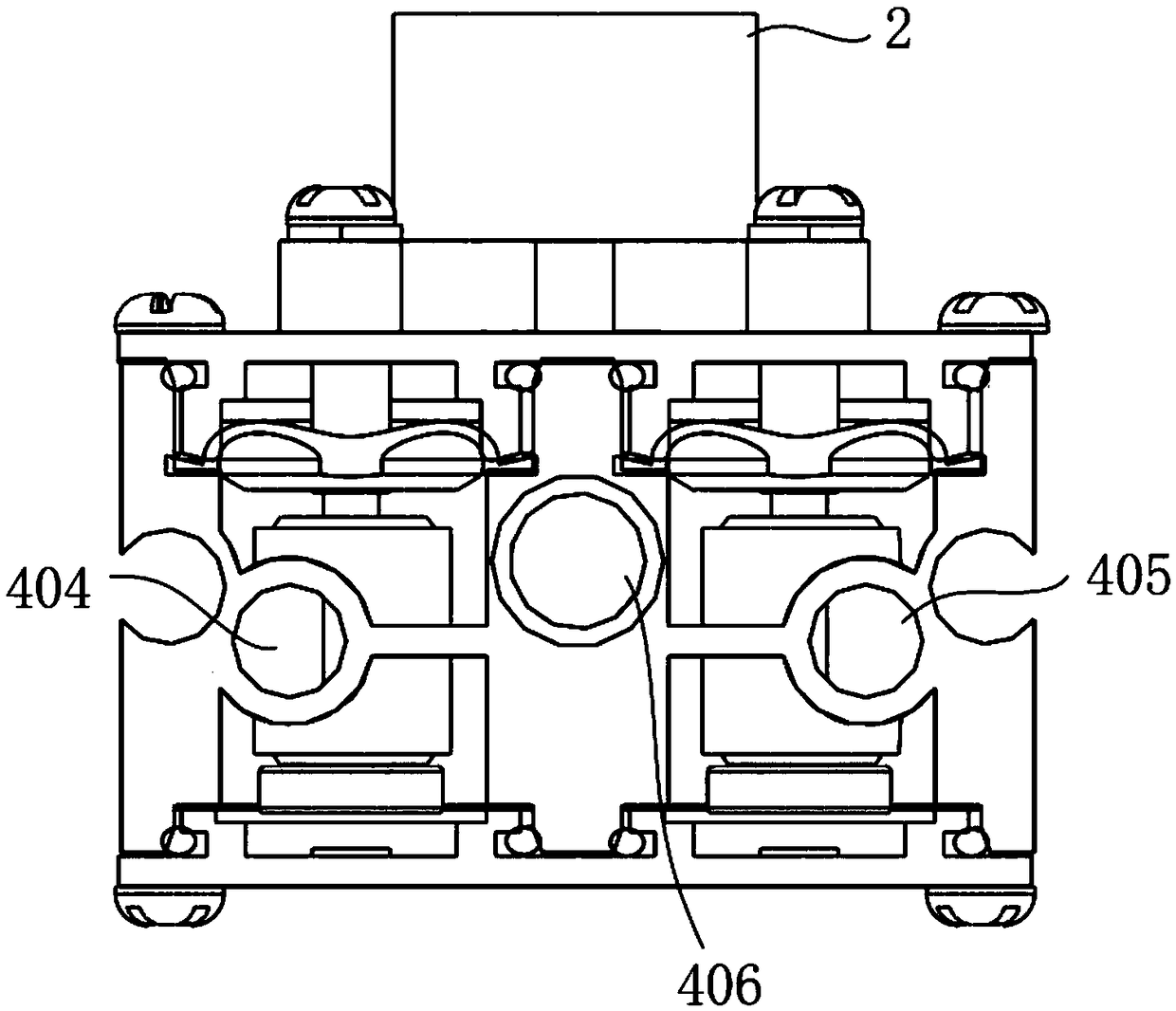
[0055] see figure 1 , Figure 5 , is a structural schematic diagram of a reversing valve, which is mainly used for valve bodies that require two or more pilot chambers to be controlled, especially in oxygen generators. The reversing valve in this embodiment includes a rotary valve core 1, a valve body 4 and a driving device 2, wherein the rotary valve core 1 includes an air inlet 105, a pressure relief port 104 and an air induction port, please refer to Figure 10 to Figure 15 , the outer contour of the rotary spool 1 is a cone shape, of course, the rotary spool 1 is not limited to the cone shape, it can also be a cylindrical shape, or other shapes, and the top of the rotary spool 1 is provided with a mounting hole 101, the installation The hole 101 extends downward from the upper surface 108 of the rotary spool and along the central axis of the rotary spool, and is a blind hole for connecting the output shaft of the drive device 2. The drive device 2 of this embodiment selec...

Embodiment 2

[0084] On the basis of Example 1, please refer to Figure 9 and Figure 18 , the valve body of the reversing valve in this embodiment includes an upper cover plate 401 and a lower cover plate 402, wherein the upper cover plate 401 has a circular protrusion extending downward above the corresponding pilot cavity, and the circular protrusion on the circular ring A side wall air-introduction channel 419 is provided on the protrusion. It is also necessary to pay special attention to that the side wall air-induction channel 419 on the annular protrusion and the aforementioned air introduction port and pressure relief port 104 are relative to the rotary valve core 1. The heights of the bottoms are equal to ensure that during the rotation of the rotary valve core 1 in the inner cavity 407, the air-introduction port and the pressure relief port-104 can be periodically connected with the inlet of the side wall air-introduction channel 419 for pressurization, or pressure relief. The c...


PUM


Abstract

The invention discloses a reversing valve and a rotating valve core thereof and belongs to the technical field of application of valves. The reversing valve comprises a valve body, a driving device and the rotating valve core; the rotating valve core comprises an air inlet, an air leading opening, a pressure relieving hole and a mounting hole; the air inlet is formed in the bottom of the rotatingvalve core and is positioned on a central axis of the rotating valve core; the air leading opening is arranged perpendicular to the central axis of the rotating valve core; the air inlet communicateswith the air leading opening; and the pressure relieving hole is arranged in a manner of penetrating through the rotating valve core and is arranged in a manner of being isolated from the air inlet. According to the reversing valve disclosed by the invention, the opening and closing of different valve chambers are controlled by utilizing the rotating valve core so that the control of the reversingvalve and a tangential valve no longer depends on an electromagnetic valve; to a valve body which needs to be controlled by two or more pivot chambers, the valve body needs not to be controlled by two or more electromagnetic valves, so the quantity of elements is reduced; and meanwhile the reversing valve disclosed by the invention is compact in structure and low in production cost.

Description

technical field [0001] The invention belongs to the technical field of valve applications, and in particular relates to a reversing valve and a rotary valve core thereof. Background technique [0002] At present, the automatic reversing and switching valves are all controlled by solenoid valves. The technology is very mature and widely used. The principle requires that each pilot chamber needs at least one solenoid valve to control the pressure change of the gas or liquid in it. For a valve body that needs to be controlled by two or more pilot chambers, a corresponding number of solenoid valves are required for control, which requires more components, lower reliability, high production cost, and large space occupation. Contents of the invention [0003] 1. Problems to be solved [0004] Aiming at the problem that multiple electromagnetic valves need to be matched with multiple electromagnetic valves to control multiple directional valves and tangential valves in the prio...

Claims


Application Information

Patent Timeline
IPC IPC(8): F16K11/20F16K31/04F16K27/06
CPCF16K11/20F16K27/062F16K31/04
Inventor 刘小祥
Owner 刘小祥
Features
  • Generate Ideas
  • Intellectual Property
  • Life Sciences
  • Materials
  • Tech Scout
  • Unparalleled Data Quality
  • Higher Quality Content
  • 60% Fewer Hallucinations
Learn More