Detecting method for iron ore sintering machine air leakage rate

A detection method and air leakage rate technology, applied in the testing of machines/structural components, measuring devices, instruments, etc., can solve problems such as large errors, inaccurate testing, and impact on sintering production

Active Publication Date: 2019-03-19
MAANSHAN IRON & STEEL CO LTD
View PDF9 Cites 9 Cited by
  • Summary
  • Abstract
  • Description
  • Claims
  • Application Information

AI Technical Summary

Problems solved by technology

[0007] In order to solve the problems of inaccurate testing, large errors, poor operability, and influence on sintering production in the above-mentioned prior art, the present invention provides a detection method for the air leakage rate of iron ore sintering machines, which improves the effective air volume in the sintering process The measurement and calculation method uses the curve integral method instead of the average value calculation, which greatly improves the accuracy of the sintering air leakage rate, and calculates the air leakage rate of the entire sintering system through the gas conservation before and after sintering, which is highly operable, fast and convenient , does not affect sintering production, thus providing a theoretical basis for sintering production to reduce energy consumption and increase output

Method used


Image

  • Detecting method for iron ore sintering machine air leakage rate
  • Detecting method for iron ore sintering machine air leakage rate
  • Detecting method for iron ore sintering machine air leakage rate

Examples


Embodiment Construction

[0076] Below in conjunction with accompanying drawing, the present invention will be further described in detail, so that those skilled in the art can understand more clearly, the method of the present invention is applied to the sintering machine air leakage rate detection of a certain factory of Maanshan Iron and Steel Co., Ltd., and the sintering machine area is 380m 2 , the trolley width is 5.2m, such as Figures 1 to 4 As shown, the specific steps are as follows:

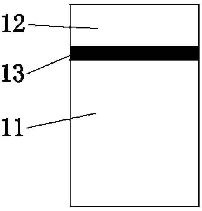
[0077] Step 1: If figure 1 As shown, take an air-introduction circular pipe 11 with an inner diameter of 120mm and a length of 350mm, and an impeller anemometer 12 with an inner diameter of 120mm is arranged on the air-induction circular pipe 11, and the upper end surface of the air-induction circular pipe 11 and the impeller anemometer 12 are lowered. A sealing ring 13 is provided between the end faces to obtain a detection device 1;

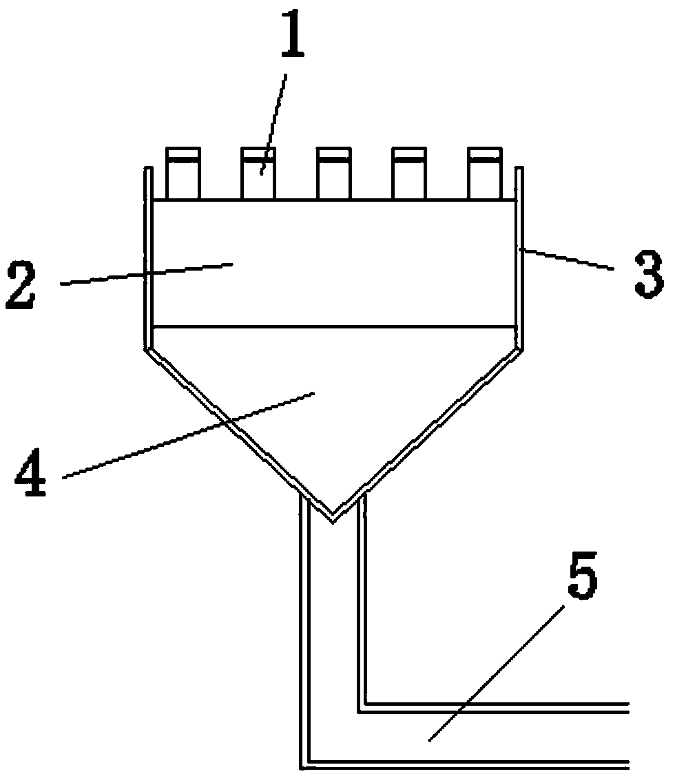
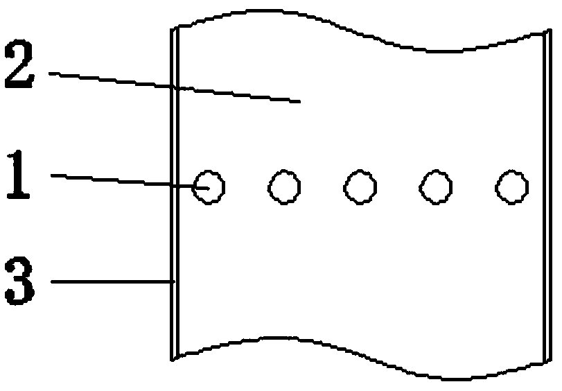
[0078] Step 2: If Figures 2 to 4 As shown, five detection devices 1 are...


PUM


Abstract

The invention discloses a detecting method for the iron ore sintering machine air leakage rate. The detection method comprises the following steps that detection devices are made firstly, and a row ofthe detection devices are arranged on a sinter bed; when sintering is conducted, wind speeds measured by all the detection devices are recorded, the material surface of the sinter bed is subjected tomesh generation, all wind speeds recorded by the detection devices from beginning to end sequentially serve as the wind speeds of all grid points on longitudinal boundary lines where the detection devices are located, and the effective air amount QY passing through the bed within unit time is calculated; the total flue gas amount QZ in a flue within unit time is calculated; the amount QE of vapour generated within the unit time is calculated; the QY, the QZ and the QE are converted into the amount under the standard state, the sintering system air leakage QLstandard within unit time is calculated, and the sintering system air leakage rate K within unit time is calculated. Accordingly, by means of an optimized sintering effective air amount measurement and calculation method, the calculation accuracy of the sintering air leakage rate is improved, maneuverability is high, rapidness and convenience are achieved, and then the theoretical basis is provided for lowering energy consumption and increasing the yield for sintering production.

Description

technical field [0001] The invention relates to the technical field of material sintering, in particular to a method for detecting the air leakage rate of an iron ore sintering machine. Background technique [0002] Sintering air leakage is a key factor affecting the energy consumption and output of sintering production. The higher the sintering air leakage rate, the less the effective air volume for sintering through the material layer, the higher the power consumption of sintering and the lower the output. Therefore, accurate measurement of the air leakage rate of the sintering system to understand the air leakage of the entire sintering system in order to find out the location of the air leakage and carry out targeted repairs, maintenance, and replacement of equipment can more effectively reduce sintering energy consumption and increase production. ,cut costs. [0003] The patent application number 201410277391.1 discloses a method for measuring the air leakage rate of ...

Claims


Application Information

Patent Timeline
Patent Type & Authority Applications(China)
IPC IPC(8): G01M99/00F27D21/00
CPCF27D21/00G01M99/008
Inventor 曹欣川洲刘自民饶磊周劲军唐嘉瑞刘其明
Owner MAANSHAN IRON & STEEL CO LTD
Why Eureka
Try Eureka