Aluminum-coated carbon fiber conductor strain clamp

A technology of aluminum-coated carbon fiber and tension-resistant clamps, applied in the field of hardware, can solve problems such as complex processing procedures, potential safety hazards of transmission lines, uneven force, etc., to avoid cutting-edge discharge phenomena, great practical and promotional value, and processing and ease of use

Pending Publication Date: 2019-03-19
JIANGSU TIANNAN ELECTRIC POWER EQUIP
View PDF0 Cites 1 Cited by
  • Summary
  • Abstract
  • Description
  • Claims
  • Application Information

AI Technical Summary

Problems solved by technology

The tension clamp is a power fitting that connects, fixes and tightens the wires on the tower. The existing transmission line conductors are generally steel-cored aluminum stranded wires. During the connection process, the steel core and the anchor of the tension clamp are crimped. During crimping, the steel core is under great pressure in the radial direction, and the force is uneven. For carbon fiber wires, the carbon fiber core is brittle, and it is easy to cause breakage under the condition of uneven force, which will cause the line to break and affect the entire wire. Line power supply, although there is a strain clamp with a threaded connection structure for the anchor and the inner pipe, one is that the processing procedure is complicated, and the other is that the joint of the clamp is prone to heat during the use of the circuit, and the vibration of the transmission line causes the thread The connection is easy to loose, which poses a safety hazard to the transmission line, so it is necessary to design an aluminum-clad carbon fiber wire tension clamp to meet the actual needs

Method used


Image

  • Aluminum-coated carbon fiber conductor strain clamp
  • Aluminum-coated carbon fiber conductor strain clamp
  • Aluminum-coated carbon fiber conductor strain clamp

Examples


Embodiment Construction

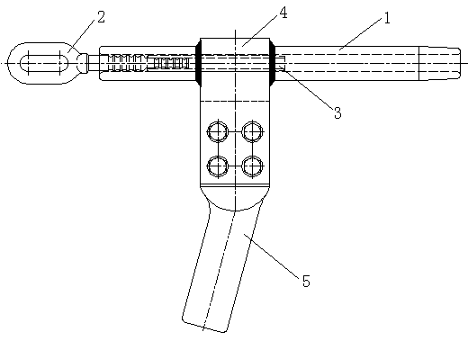
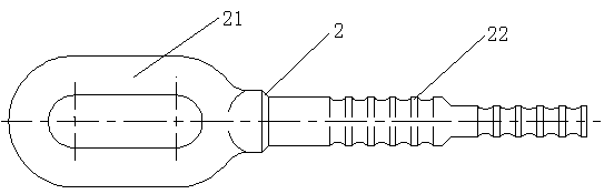
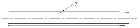
[0016] Refer to attached figure 1 , attached figure 2 , attached image 3 , attached Figure 4 , an aluminum-clad carbon fiber wire tension clamp of the present invention is composed of a clamp body 1, a steel anchor 2, a crimping tube 3, a drain plate 4, and a drain clamp 5, and the clamp body 1 is a hollow tubular structure , the inner diameter of the tube matches the outer diameter of the aluminum-coated carbon fiber conductor; one end of the clamp body 1 is crimped with a steel anchor 2, and the other end is crimped with an aluminum-coated carbon fiber conductor; the clamp body 1 is crimped with the aluminum-coated carbon fiber conductor The outside of the connection end is a tapered structure; the two ends of the clamp body 1 are arc-shaped surfaces; the drain plate 4 is provided on the clamp body 1; one end of the drain clamp 5 is connected to the drain plate 4 through a bolt, and the other end It is crimped with the jumper; one end of the steel anchor 2 is a pull ri...


PUM


Abstract

The invention relates to an aluminum-coated carbon fiber conductor strain clamp, which is composed of a clamp body, a steel anchor, a compression pipe, a drainage plate and a drainage clamp, wherein the ratio of lengths of insertion to the compression pipe by an anchor rod and an aluminum-coated carbon fiber core is 1 to 2; as two end surfaces of the clamp body adopt a circular arc surface structure form, happening of a point discharge phenomenon is thus avoided; as the compression outer surface between the clamp body and the aluminum-coated carbon fiber conductor adopts a taper structure, stress concentration after compression is thus avoided; as the anchor rod of the steel anchor is uniformly provided with annular circular arc grooves, the compression pipe and the anchor rod and the anchor rod and the clamp body after compression can be closely fit, and the tension resistance is improved; as the drainage plate adopts a ring buckle and splint combination mode and the drainage plate and the drainage clamp are in double-sided contact, the conductive performance is better; and the compression part between the compression pipe and the aluminum-coated carbon fiber core adopts the taperstructure, stress concentration after compression to cause damages to the carbon fiber core can be avoided.

Description

technical field [0001] The invention relates to fittings for power transmission and distribution lines in the electric power industry, in particular to an aluminum-coated carbon fiber wire tension clamp. Background technique [0002] After retrieving relevant patent documents, no aluminum-clad carbon fiber wire tension clamp with the same structure as the present invention has been retrieved. The tension clamp is a power fitting that connects, fixes and tightens the wires on the tower. The existing transmission line conductors are generally steel-cored aluminum stranded wires. During the connection process, the steel core and the anchor of the tension clamp are crimped. During crimping, the steel core is under great pressure in the radial direction, and the force is uneven. For carbon fiber wires, the carbon fiber core is brittle, and it is easy to cause fracture under the condition of uneven force, which will cause the line to break and affect the entire wire. Line power s...

Claims


Application Information

Patent Timeline
Patent Type & Authority Applications(China)
IPC IPC(8): H02G7/02H01R4/20H01R11/12
CPCH02G7/02H01R4/20H01R11/12
Inventor 姚建生周游朱小强田书鹏周翼翔史小龙
Owner JIANGSU TIANNAN ELECTRIC POWER EQUIP
Why Eureka
Try Eureka