Piezoelectric MEMS microphone

A microphone and piezoelectric technology, applied in the field of piezoelectric MEMS microphones, can solve problems such as uneven stress distribution, uneven deformation, affecting microphone sensitivity and anti-drop performance, so as to improve uniformity, reduce structural differences, Effect of improving drop resistance

Active Publication Date: 2019-03-19
AAC ACOUSTIC TECH (SHENZHEN) CO LTD
View PDF4 Cites 30 Cited by
  • Summary
  • Abstract
  • Description
  • Claims
  • Application Information

AI Technical Summary

Problems solved by technology

[0006] Aiming at the technical problem in the related art that the free end of the diaphragm of the piezoelectric MEMS microphone is unevenly deformed due to uneven stress distribution during the processing process, thereby affecting the sensitivity and anti-drop performance of the microphone, the present invention provides a novel structure Piezoelectric MEMS Microphone

Method used


Image

  • Piezoelectric MEMS microphone
  • Piezoelectric MEMS microphone
  • Piezoelectric MEMS microphone

Examples


Embodiment 1

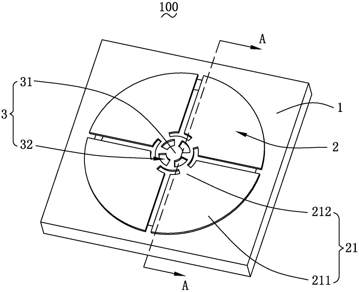
[0025] Please refer to image 3 and Figure 4 , the present invention provides a piezoelectric MEMS microphone 100, which includes a substrate 1 with a back cavity 10, a piezoelectric diaphragm 2 disposed on the substrate 1, and a constraint located in the central region of the piezoelectric diaphragm 2 Structure 3. The base 1 is made of semiconductor material, such as silicon, and the back cavity 10 runs through the base 1 longitudinally, wherein the back cavity 10 can be formed by bulk silicon process or dry etching. The cross-sectional area of ​​the back cavity 10 is smaller than that of the piezoelectric diaphragm 2 , and the cross-sectional area of ​​the constraint structure 3 is smaller than that of the back cavity 10 .

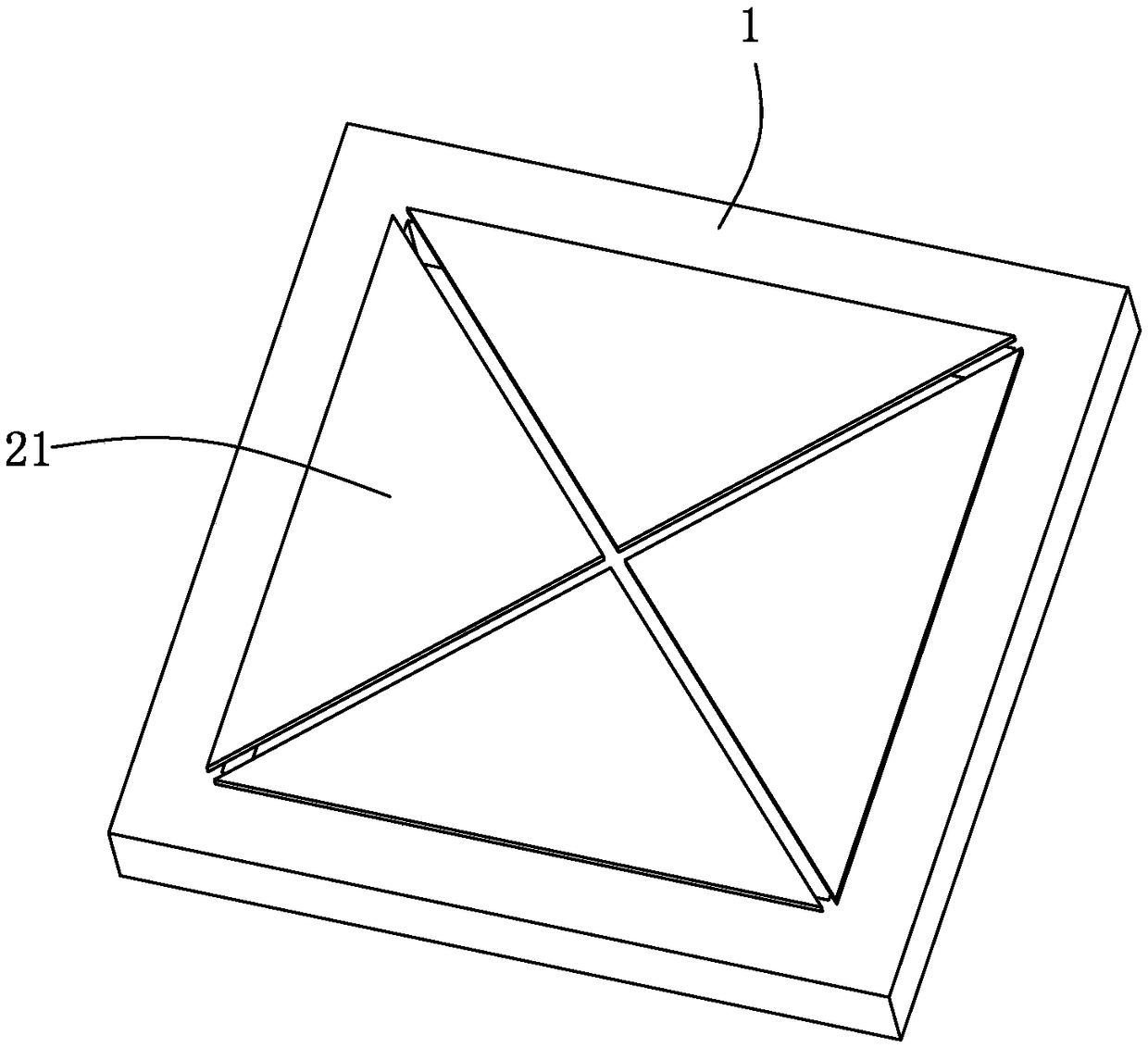
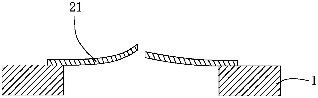
[0026] The piezoelectric vibrating film 2 is generally circular, and its periphery is fixed to the base 1 , and other parts are suspended above the back cavity 10 of the base 1 . The piezoelectric diaphragm 2 includes a plurality of diaphragms 21 . ...

Embodiment 2

[0032] see Figure 5 , the piezoelectric MEMS microphone 200 provided in this embodiment is substantially the same as the piezoelectric MEMS microphone 100 in Embodiment 1, the main difference is that a plurality of the diaphragms 21 cooperate with the constraining structure 3 to form a square structure . The piezoelectric diaphragm 2 includes four diaphragms 21 , and the constraining structure 3 located in the central area of ​​the piezoelectric diaphragm 2 is a square mesh structure. The other structures are substantially the same and will not be repeated here.

[0033] Compared with the related art, the piezoelectric MEMS microphone of the present invention restricts the free end 212 of the diaphragm 21 in the same plane by setting the constraint structure 3, when the diaphragm 21 is released from the base 1, the The constraint structure 3 can limit the degree of deformation of the diaphragm 21, so that the gap between two adjacent diaphragms 21 is consistent, reducing the...


PUM


Abstract

The invention provides a piezoelectric MEMS microphone, comprising a substrate having a rear cavity, and a piezoelectric diaphragm disposed on the substrate. The piezoelectric diaphragm comprises a plurality of diaphragms, each of the diaphragms comprises a fixed end connected to the substrate and a free end connected to the fixed end and suspended above the rear cavity, and adjacent two of the diaphragms are spaced or in contact with each other. The piezoelectric EMES microphone further comprises a constraining structure at a central region of the piezoelectric diaphragm, and free ends of atleast two of the diaphragms are connected to the constraining structure. Compared with the related art, the piezoelectric MEMS microphone limits the free ends of the diaphragms in the same plane by the constraining structure, thereby improving the uniformity of product performance and the anti-drop performance.

Description

【Technical field】 [0001] The invention relates to the field of acoustic and electric technologies, in particular to a piezoelectric MEMS microphone. 【Background technique】 [0002] In recent years, more and more mobile devices begin to use Micro Electro Mechanical System (MEMS) microphones instead of the original electret microphones. Due to the changing environment of mobile devices, this puts forward higher requirements for the reliability of MEMS microphones. [0003] At present, MEMS microphones are mainly divided into capacitive MEMS microphones and piezoelectric MEMS microphones. Piezoelectric MEMS microphones can overcome some shortcomings of traditional capacitive MEMS microphones, have better performance in dustproof and waterproof, and have a wider range of applications. Different from the diaphragm structure of condenser microphones, such as figure 1 As shown, the diaphragm of the piezoelectric MEMS microphone is composed of a plurality of diaphragms 21, one en...

Claims


Application Information

Patent Timeline
Patent Type & Authority Applications(China)
IPC IPC(8): H04R17/02
CPCH04R17/02H04R2201/003
Inventor 段炼张睿
Owner AAC ACOUSTIC TECH (SHENZHEN) CO LTD
Why Eureka
Try Eureka