Film-covered stent expander

A covered stent and spreader technology, applied in stents, suction devices, blood vessels, etc., can solve problems such as insufficient blood flow, and achieve the effects of easy use, easy promotion, and simple structure

Pending Publication Date: 2019-03-22
WUXI PEOPLES HOSPITAL
View PDF0 Cites 2 Cited by
  • Summary
  • Abstract
  • Description
  • Claims
  • Application Information

AI Technical Summary

Problems solved by technology

[0004] The purpose of the present invention is to provide a stent graft spreader to solve the problem of insufficient blood flow due to the limitation of the diameter of the diverter sheath when the stent graft is used in the above background technology

Method used


Image

  • Film-covered stent expander
  • Film-covered stent expander
  • Film-covered stent expander

Examples


Embodiment 1

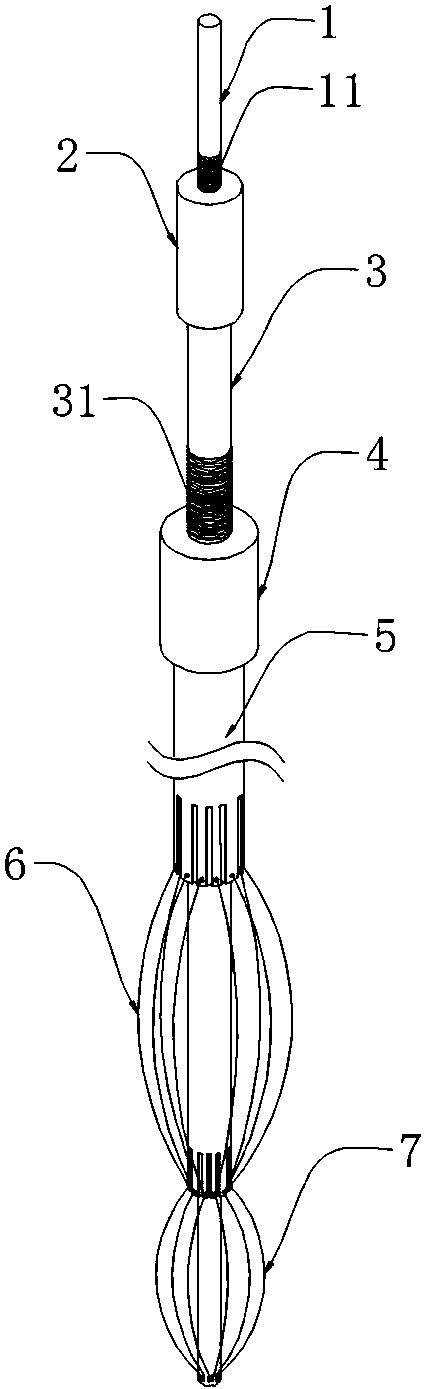
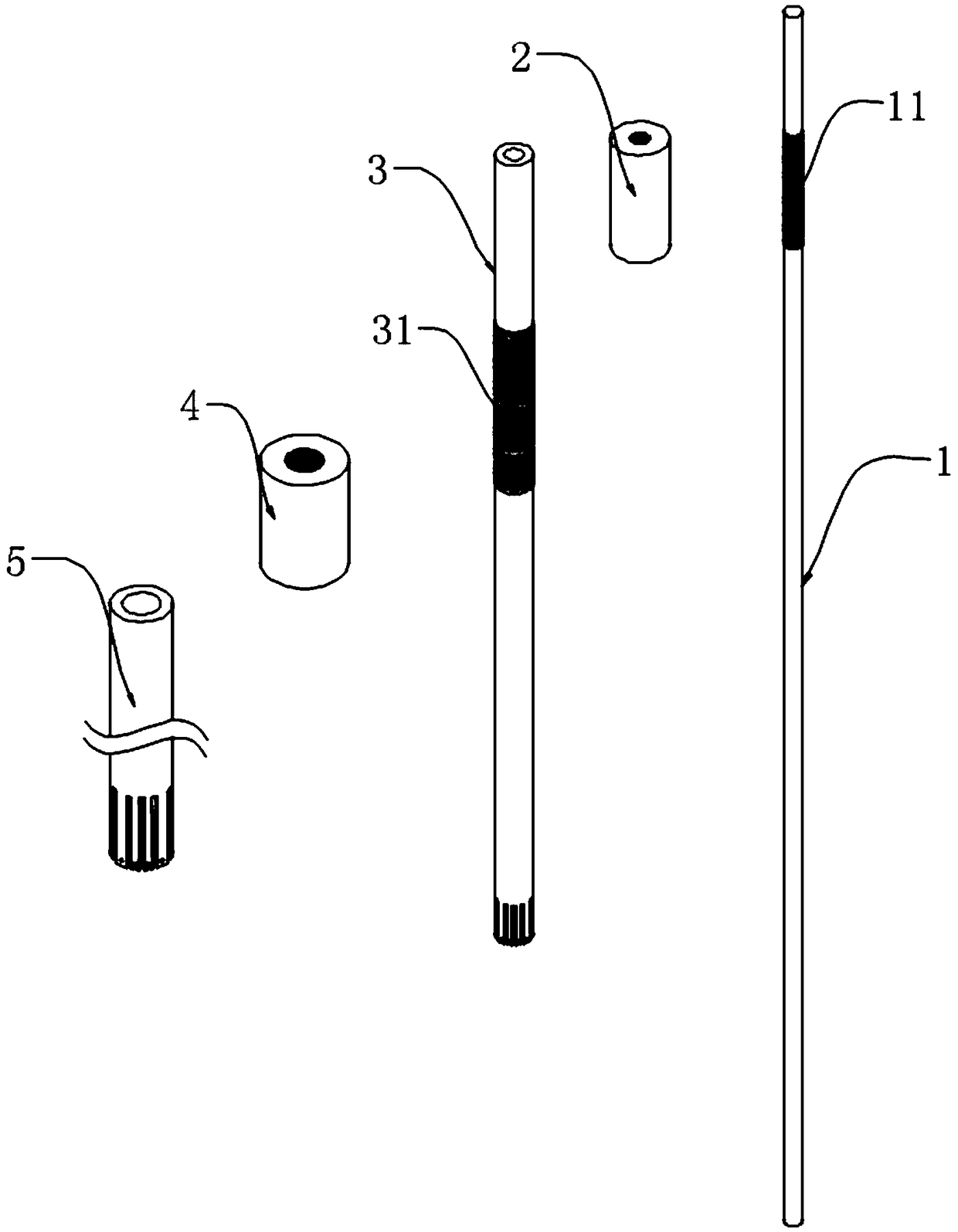
[0024] A stent graft spreader, comprising a core rod 1, such as figure 1 , figure 2 As shown, the outer wall of one end of the core rod 1 is provided with a first external thread 11, and the center rod advance and retreat adjustment nut 2 is provided on the core rod 1 close to the first external thread 11, and the center rod advance and retreat adjustment nut 2 is threadedly connected with the core rod 1, The middle part of the core rod 1 is provided with a movable middle rod 3, the length of the core rod 1 is greater than the length of the movable middle rod 3, the movable middle rod 3 is slidingly connected with the core rod 1, and the outer wall of the middle part of the movable middle rod 3 is provided with a second external thread 31. An outer rod advance and retreat adjustment nut 4 is provided near the second external thread 31 on the movable middle rod 3, and the outer rod advance and retreat adjustment nut 4 is threadedly connected with the movable middle rod 3, and ...

Embodiment 2

[0031] In the specific use process, the movable outer rod 5 and the movable middle rod 3 are prone to rotate when sliding, thereby causing the first expansion skeleton 6 and the second expansion skeleton 77 to be twisted, and it is easy to cause fracture and damage after long-term use. Therefore, we Improvement is made on the basis of embodiment 1, as Figure 4 and Figure 5 As shown, one end of the movable outer rod 5 and the movable middle rod 3 are provided with several radial grooves 51 close to the first expansion skeleton 6, and the outer surface of the movable middle rod 3 is tightly welded with the limit block 32 near the radial groove 51. , the limit block 32 is slidably connected with the radial groove 51, and one end of the movable outer rod 5 and the movable middle rod 3 is also provided with several annular grooves 52 near the first expansion skeleton 6, and the inside of the annular groove 52 is embedded with an annular wire 521, the annular wire 521 is tightly ...


PUM


Abstract

The invention relates to the technical field of covered stents, in particular to a film-covered stent expander which comprises a mandrel. The outer wall of one end of the mandrel is provided with a first external thread, a middle rod advancing and retreating adjusting nut is arranged at a position, close to the first external thread, of the mandrel, a moving middle rod sleeves the middle of the mandrel, a second external thread is arranged on the outer wall of the middle of the moving middle rod, an outer rod advancing and retreating adjusting nut is arranged at a position, close to the secondexternal thread, of the moving middle rod, a moving outer rod sleeves the middle of the moving middle rod, a plurality of first expansion frameworks are arranged on the bottom outer wall of the moving middle rod, and a plurality of second expansion frameworks are arranged on the bottom outer wall of the mandrel. The film-covered stent expander is simple in structure and convenient to use and canexpand the first expansion frameworks and the second expansion frameworks so as to expand a film-covered stent, in this way, blood can leak through from space between an aorta wall and the film-covered stent to reach innominate artery and then goes to left carotid artery from an artificial vascular bypass, and blood flow can be guided into original blood vessels, so that blood flow insufficiency is avoided.

Description

technical field [0001] The invention relates to the technical field of stent grafts, in particular to a stent graft spreader. Background technique [0002] At present, part of type A aortic dissection can be performed without thoracotomy and cardiopulmonary bypass, and can also be treated with minimally invasive intracavitary stents to seal the breach of the dissection. The endoluminal covered stent covers the three branches of the aortic arch. The proximal end of the covered stent will be located in the ascending aorta, and the distal end will be located in the descending aorta. At this point in the process, the blood supply to the brain is completely blocked. In order to supply blood to the brain, a bypass sheath needs to be placed between the wall of the ascending aorta and the stent graft of the ascending aorta to guide the blood flow to the carotid artery. The stent is in the shape of a cylinder as a whole and consists of a metal skeleton and thin blood vessels covered...

Claims


Application Information

Patent Timeline
Patent Type & Authority Applications(China)
IPC IPC(8): A61F2/07A61M1/36
CPCA61M1/3655A61F2/07
Inventor 原野
Owner WUXI PEOPLES HOSPITAL
Why Eureka
Try Eureka