
Cotton thread spring forming equipment

A technology of forming equipment and cotton thread, which is applied in the direction of making springs from threads, wire processing, textiles and papermaking, etc. Fitting, high machining accuracy, and achieving precise control effects

Pending Publication Date: 2019-03-22
KUNSHAN BAIAO INTELLIGENT EQUIP CO LTD
View PDF0 Cites 0 Cited by
  • Summary
  • Abstract
  • Description
  • Claims
  • Application Information

AI Technical Summary

Problems solved by technology

When using the traditional spring machine to process the core part, due to the limitation of the forming principle, it is not only necessary to add lubricating oil to cause pollution of the resistance wire, but also the forming inner diameter of the resistance wire needs to be larger than the outer diameter of the cotton thread, otherwise cotton thread and metal wire will be produced intertwined
However, if the forming inner diameter of the resistance wire is larger than the outer diameter of the cotton thread, the resistance wire may move along the axis of the cotton thread, and it will also affect the heating effect of the resistance wire.

Method used


Image

  • Cotton thread spring forming equipment
  • Cotton thread spring forming equipment
  • Cotton thread spring forming equipment

Examples


Embodiment Construction

[0055]A preferred embodiment of the present invention will be described in detail below in conjunction with the accompanying drawings. However, the scope of protection of the present invention is not limited to the following examples, that is, any simple equivalent changes and modifications made based on the patent scope of the present invention and the content of the description are still within the scope of the patent of the present invention.

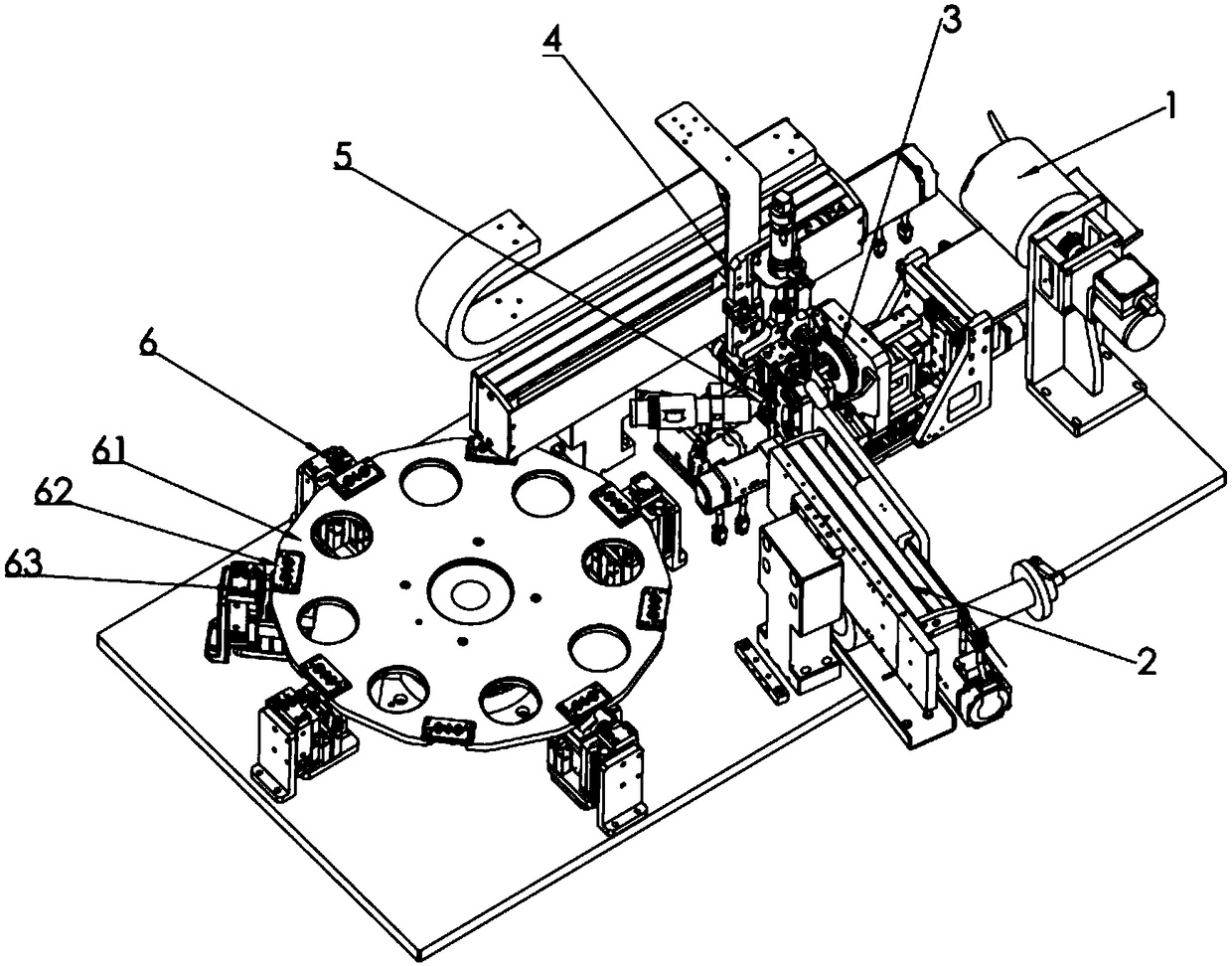
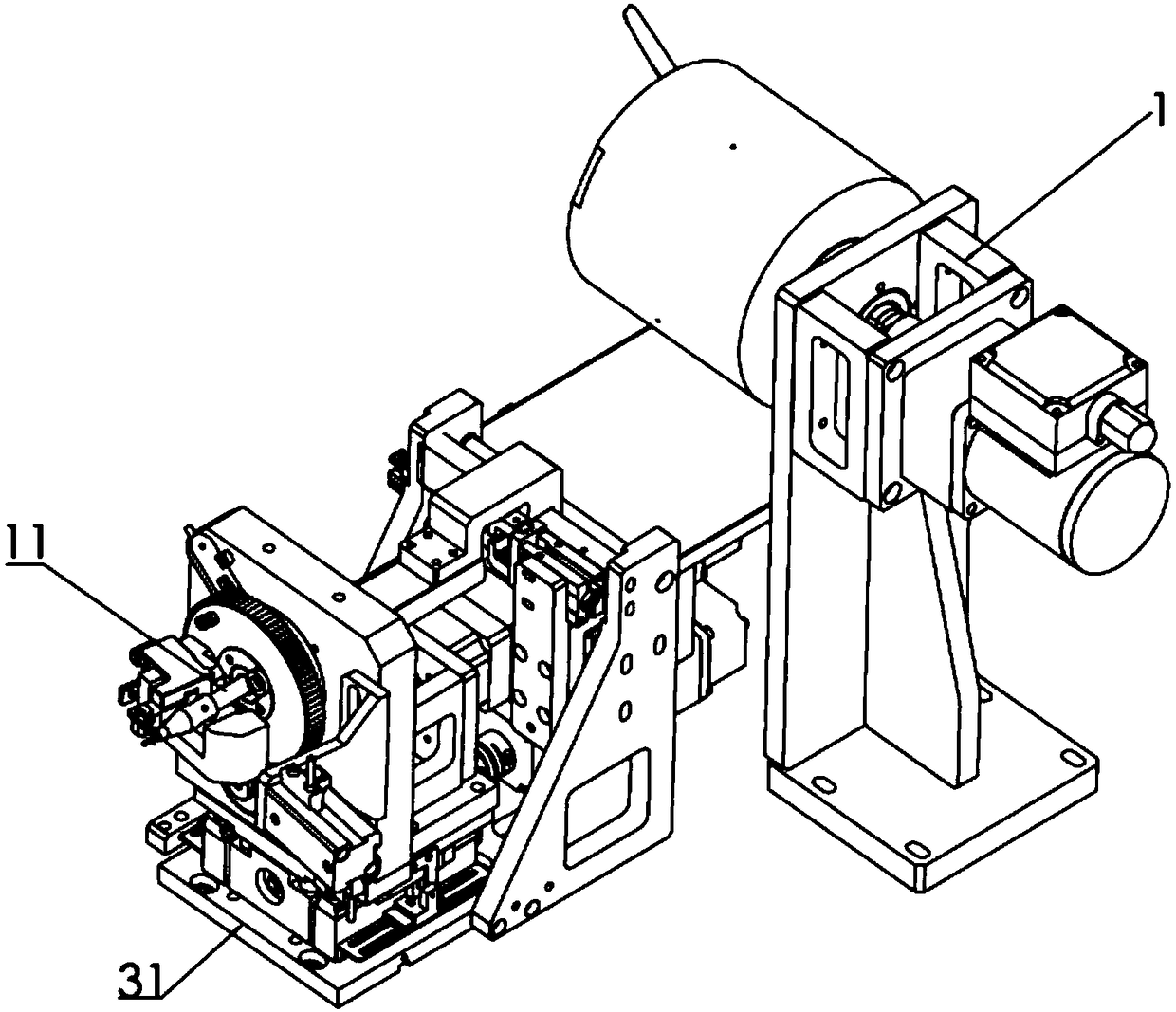
[0056] refer to Figure 1-10 , is a cotton thread spring forming device according to the present invention, comprising a wire feeding mechanism 1, a wire feeding mechanism 2, a wire winding mechanism 3, a handling mechanism 4, a cutting mechanism 5 and a carrier assembly 6, and the wire winding mechanism The metal wire conveyed by the wire feeding mechanism is spirally formed, and the conveying mechanism assembles and conveys the formed metal wire and cotton thread. It is characterized in that: the wire winding mechanism is arranged ...


PUM


Abstract

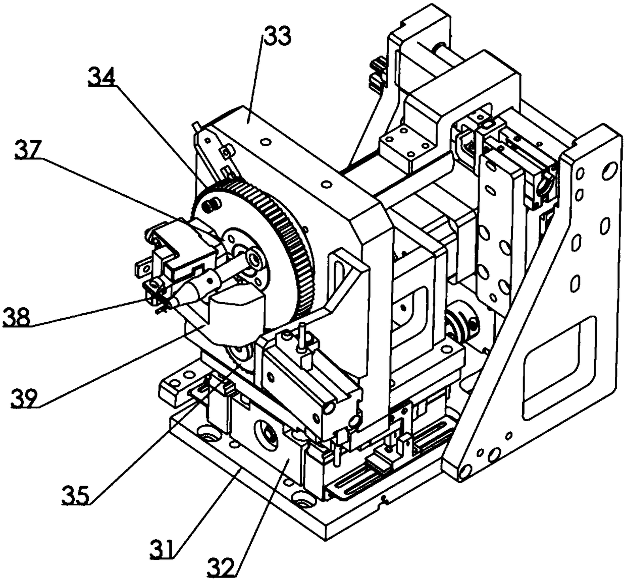
The invention discloses cotton thread spring forming equipment. The cotton thread spring forming equipment comprises a thread feeding mechanism, a wire feeding mechanism, a winding mechanism, a carrying mechanism, a cropping mechanism and a carrier assembly. The winding mechanism comprises a winding bottom plate, a screw pitch module, a vertical plate, a large gear, a winding drive gear and a winding sleeve, and the screw pitch module can drive the vertical plate to move front and back. The center of the vertical plate is provided with a main shaft through a bearing in an erected manner, wherein the main shaft can rotate relative to the vertical plate, and the large gear is fixed to the main shaft and is in meshing connection with the winding drive gear. A through hole is formed in the center of the main shaft. A cotton thread conveying rod of the thread feeding mechanism penetrates out of the through hole of the main shaft, and the winding sleeve fixedly sleeves the outer end of the cotton thread conveying rod. The cotton thread spring forming equipment is high in machining precision, screw pitch adjustment is convenient, lubricating oil filling is not needed, the spiral inner diameter of a metal wire can be smaller than the outer diameter of a cotton thread in a free state, tight attachment of the metal wire and the cotton thread is achieved, and accordingly accurate controlover the effective resistance value and the heating effect of a resistance wire is achieved.

Description

technical field [0001] The invention belongs to the technical field of automatic processing equipment, and in particular relates to a cotton thread spring forming equipment. Background technique [0002] When the core component of the electronic cigarette device is processed, the resistance wire needs to be spirally formed on the cotton thread. When using the traditional spring machine to process the core part, due to the limitation of the forming principle, it is not only necessary to add lubricating oil to cause pollution of the resistance wire, but also the forming inner diameter of the resistance wire needs to be larger than the outer diameter of the cotton thread, otherwise cotton thread and metal wire will be produced intertwined. However, if the forming inner diameter of the resistance wire is larger than the outer diameter of the cotton thread, the resistance wire may move along the axis of the cotton thread, and the heating effect of the resistance wire will also b...

Claims


Application Information

Patent Timeline
Patent Type & Authority Applications(China)
IPC IPC(8): B21F35/00B21F23/00B21F3/04D06H7/00
CPCD06H7/00B21F3/04B21F23/00B21F35/00
Inventor 吕术三刘伟冬王浩宋俊朋张孟王政
Owner KUNSHAN BAIAO INTELLIGENT EQUIP CO LTD
Learn More