Device and method for vibration assisting of hot embossing

A technology of hot imprinting and regulating device, applied in the field of nano imprinting, can solve the problems of reducing imprinting rate, template and substrate damage, consumption, etc., and achieve the effect of speeding up cooling rate, acceleration rate, and cost reduction

Pending Publication Date: 2019-03-22
CHANGCHUN UNIV OF TECH
View PDF6 Cites 3 Cited by
  • Summary
  • Abstract
  • Description
  • Claims
  • Application Information

AI Technical Summary

Problems solved by technology

However, before the central region reaches the viscoelastic temperature, the dissipation of temperature in the corner regions will reduce its imprinting rate
Moreover, during the cooling process, the temperature in the central area is relatively high, resulting in huge thermal stress, which will cause certain damage to the template and the substrate, and it is not easy to cool down during the cooling process, and it takes a long time to drop to the demoulding temperature. It is easy to cause damage to the template and substrate, and affects the imprinting rate
The patent with the publication number CN 1586894 A discloses a Peltier thermal cycle micro-nano imprinting device, which uses the Peltier thermal cycle, shortens the time of heating and cooling, improves the efficiency of imprinting, and precisely controls the temperature, but ignores the problem of relatively slow cooling in the central area of ​​the polymer, and consumes more energy than the magnetocaloric effect, and the cost is relatively high

Method used


Image

  • Device and method for vibration assisting of hot embossing
  • Device and method for vibration assisting of hot embossing
  • Device and method for vibration assisting of hot embossing

Examples


Embodiment Construction

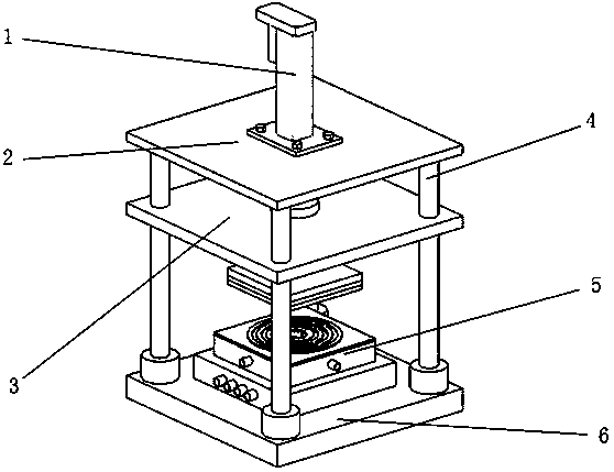
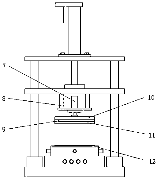
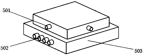
[0026] Such as figure 1 , 2 As shown, the vibration-assisted hot embossing device includes an electric control rod 1, an upper base plate 2, a sliding plate 3, a guide rod 4, a temperature control device 5, a lower base plate 6, an ultrasonic generating device 7, and a support frame 8 , heating plate 9, bearing plate 10, vacuum sucker one 11 and vacuum sucker two 12, wherein, the temperature control device 5 is fixed on the lower base plate 6, the temperature control device 5 is provided with vacuum sucker two 12, and the sliding plate 3 passes through the guide Rod 4, the lower end of guide rod 4 is fixed on the lower base plate 6, the upper end is connected with the upper base plate 2, the electric control rod 1 is fixed on the upper base plate 2 by screws, the lower end of the electric control rod 1 is connected with the sliding plate 3, and the ultrasonic generating device 7 Fixed on the support frame 8 by screws, the lower end of the ultrasonic generating device 7 is con...


PUM


Abstract

The invention discloses a device and method for vibration assisting of hot embossing. The device is composed of an electric control rod, an upper bottom plate, a sliding plate, guide rods, a temperature regulation and control device, a lower bottom plate, a supporting frame, an ultrasonic generation device, a load bearing plate, a heating plate, a first vacuum suction cup and a second vacuum suction cup. A template is fixed to the first vacuum suction cup. A substrate is fixed to the second vacuum suction cup. The template and the substrate are preheated, and pre-pressing is conducted after heating is conducted to the assigned temperature. An ultrasonic vibrator is used for applying ultrasonic vibration, the temperature regulation and control device is coordinated to heat a polymer on thesubstrate to the glass transition temperature, then, embossing is conducted, and after embossing is finished, the temperature regulation and control device is used for cooling and curing, and demoulding is finished. According to the device and method for vibration assisting of hot embossing, the polymer forming rate is increased, template and substrate damage is reduced, and the needed cost is reduced.

Description

technical field [0001] The invention relates to the field of nano-imprinting, in particular to a vibration-assisted thermal embossing device and method. Background technique [0002] Nanoimprint lithography technology was proposed by Chinese scientist Zhou Yu in 1995. Due to its low cost and parallel processing advantages, it has become the main method for processing semiconductor devices, optical devices, self-cleaning glass and other devices. At present, the mainstream imprinting technologies include ultraviolet imprinting technology, thermal embossing technology and micro-contact imprinting technology. Among them, thermal embossing technology has the advantage of high resolution compared with ultraviolet imprinting technology and micro-contact imprinting technology. However, the environment required for hot embossing is relatively harsh. After vacuuming, the polymer is heated above the glass transition temperature, and the micro-nano structure on the mold is transferred ...

Claims


Application Information

Patent Timeline
Patent Type & Authority Applications(China)
IPC IPC(8): B29C51/18B29C51/42G03F7/00
CPCG03F7/0002B29C51/18B29C51/421
Inventor 谷岩林洁琼韩金国张群孙慧岩李景鹏郑恭承曹东旭刘阳孙彦东全威龙易正发戴得恩冯开拓
Owner CHANGCHUN UNIV OF TECH
Why Eureka
Try Eureka