Steel pipe high strength concrete column reinforcing joint and method for manufacturing same

A high-strength concrete, beam-column connection technology, applied in columns, piers, pillars, etc., can solve the problems of difficult welding quality assurance, inconvenient construction, large workload, etc. The effect of seismic requirements

Inactive Publication Date: 2002-11-27
SOUTH CHINA UNIV OF TECH
View PDF0 Cites 5 Cited by
  • Summary
  • Abstract
  • Description
  • Claims
  • Application Information

AI Technical Summary

Problems solved by technology

[0003] The purpose of the present invention is to overcome and solve the shortcomings and problems of existing steel reinforced ring joints, such as very large on-site welding workload, inconvenient construction, and difficult guarantee of welding quality, and research and design a kind of joint with reasonable force and good reliability. High-strength concrete steel column joint for beam-column connection with convenient construction and easy quality control and manufacturing method thereof

Method used


Image

  • Steel pipe high strength concrete column reinforcing joint and method for manufacturing same
  • Steel pipe high strength concrete column reinforcing joint and method for manufacturing same
  • Steel pipe high strength concrete column reinforcing joint and method for manufacturing same

Examples


Embodiment 1

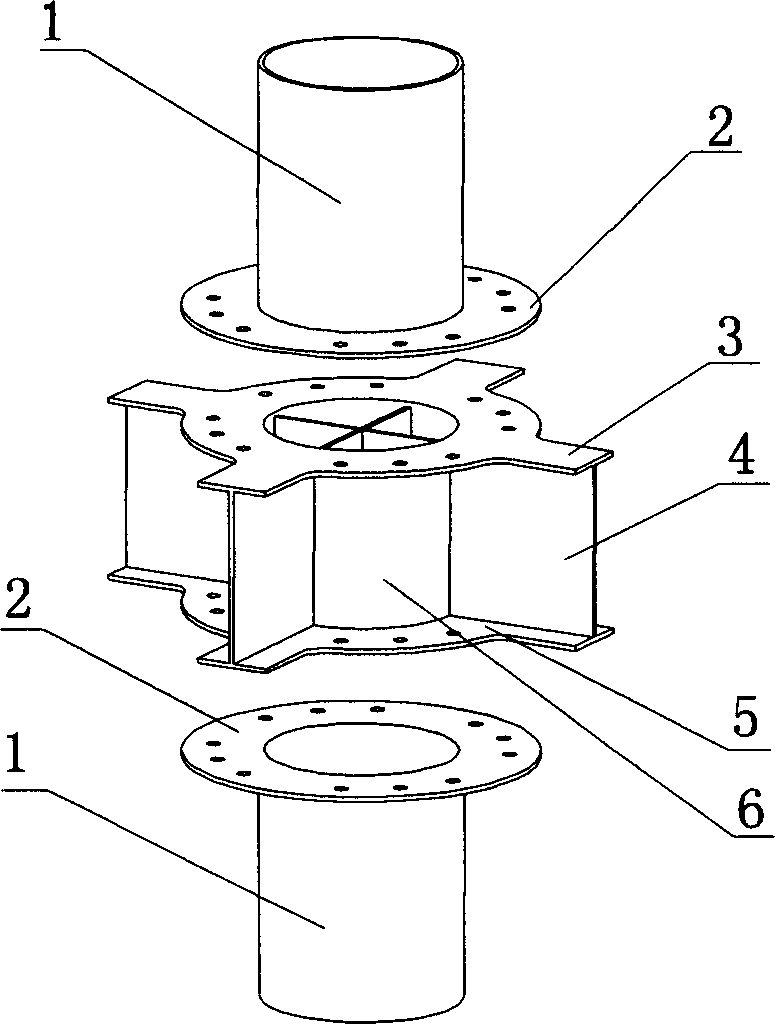
[0015] according to figure 1 As shown, the lengths of the two sections made of steel plates are h 1 and h 2 The steel pipe 6 of the node section and the steel pipe 1 of the column body section, where h 1 Equal to the beam height h of the concrete beam at the joint section b The remaining height after subtracting the thickness of the upper and lower concrete protective layers, h 2 Equal to floor height h minus h 1 remaining height; press Figure 4 with Figure 5 As shown, the flange ring 2, the pull ring 3 and the pressure ring 5 are cut out on a steel plate, and the flange ring 2 is stacked with the pull ring 3 and the pressure ring 5 to drill out Figure 4 with Figure 5 Bolt holes shown; press figure 1 As shown, the "ten"-shaped through-heart web 4 is made of a steel plate; the node segment steel pipe 6 is as figure 1 Cut the four sides as shown; weld the steel pipe 6 of the node section with the "ten"-shaped piercing web 4; respectively weld the pull ring 3 and the...

Embodiment 2

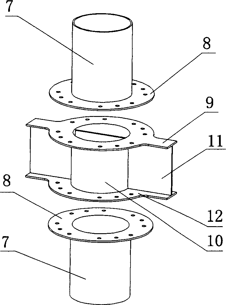
[0017] according to figure 2 As shown, two sections of length h are made with spiral coiled tube 1 and h 2 The steel pipe 10 of the node section and the steel pipe 7 of the column body section, where h 1 Equal to the beam height h of the concrete beam at the joint section b The remaining height after subtracting the thickness of the upper and lower concrete protective layers, h 2 Equal to floor height h minus h 1 the remaining height; press Figure 6 with Figure 4 As shown, the pull ring 9, the pressure ring 12 and the flange ring 8 are cut out on a steel plate, and the flange ring 8 is stacked with the pull ring 9 and the pressure ring 12 to drill out such as Figure 4 with Figure 6 Bolt holes shown; press figure 2 As shown, make a "one"-shaped through-heart web 11 with a steel plate; figure 2 Cut the two sides as shown; weld the steel pipe 10 of the node section with the "one"-shaped through-heart web 11; weld the pull ring 9 and the compression ring 12 with th...


PUM


Abstract

The invention provides a steel pipe high-strength concrete column joint for beam-column connection and a manufacturing method thereof. The high-strength concrete steel tube column joint is composed of two parts: the column body and the joint section; the manufacturing method of the steel tube high-strength concrete column joint is that the joint section includes the joint section steel pipe, pull ring, pressure ring and piercing web, and the column body includes the steel pipe and flange of the column body section Ring; during installation, the end face of the pull ring and the end face of the pressure ring of the node section are respectively fitted with the end face of the flange ring of the column body, and the node section is connected with the column body by high-strength bolts. The steel pipe high-strength concrete column joint has reasonable stress, clear force transmission, good reliability, convenient construction, and easy control of welding quality.

Description

(1) Technical field [0001] The invention relates to a steel pipe high-strength concrete column joint used for beam-column connection and a manufacturing method thereof, which belongs to the manufacturing technology of steel pipe concrete structures. (2) Background technology [0002] Concrete filled steel pipe is a new type of composite structural material with high bearing capacity, good plasticity and toughness, cost saving, and convenient construction. It has been used in industrial and civil construction projects for many years, and has achieved good technical and economic benefits. Steel tube high-strength concrete is a component that uses high-strength steel plates rolled together with high-strength concrete above C60 to work together. Its failure state and working mechanism are similar to steel tube ordinary concrete, but its strength has been greatly improved. Elasticity The working range is increased, and the ductility requirements of the structure can be fully met ...

Claims


Application Information

Patent Timeline
Patent Type & Authority Patents(China)
IPC IPC(8): E04B1/19E04C3/34
Inventor 梁启智骆伟张力张耀华徐彬张正先
Owner SOUTH CHINA UNIV OF TECH
Why Eureka
Try Eureka