Method and apparatus for controlling light

A control device and a technology for controlling light, which is applied in the field of controlling light, can solve the problems of loss and damage, etc.

Inactive Publication Date: 2002-11-27
迪科公司
View PDF4 Cites 0 Cited by
  • Summary
  • Abstract
  • Description
  • Claims
  • Application Information

AI Technical Summary

Problems solved by technology

A further disadvantage is that the system is vulnerable to wear and tear, and the electrical control lines and some of the shutters locally must be carefully packaged

Method used


Image

  • Method and apparatus for controlling light
  • Method and apparatus for controlling light
  • Method and apparatus for controlling light

Examples


Embodiment Construction

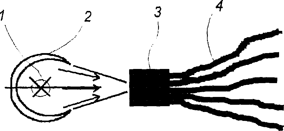
[0092] Figure 1a A bulb or light source 1 is shown, with its associated reflector 2 positioned so that the light emitted by the light source 1 is directed towards the control device 3 in a suitable manner. This light is distributed to a plurality of optical waveguides 4 in a control device 3 which, in addition to distributing this light to the optical waveguides 4, is able to switch on, off and dim the light in the individual optical waveguides 4.

[0093] These optical waveguides generally refer to some optical fibers, self-focusing optical waveguides, and the like.

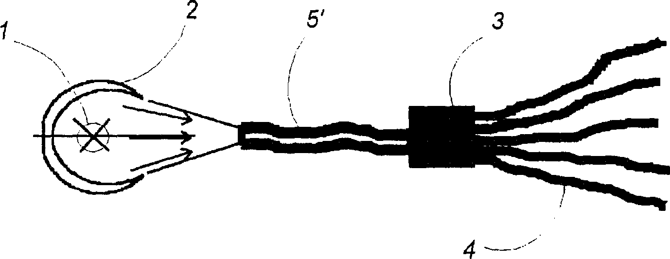
[0094] Figure 1b represents another embodiment of the invention, in which light is directed from the light source to the control device 3 via an optical waveguide or bundle of optical waveguides 5 .

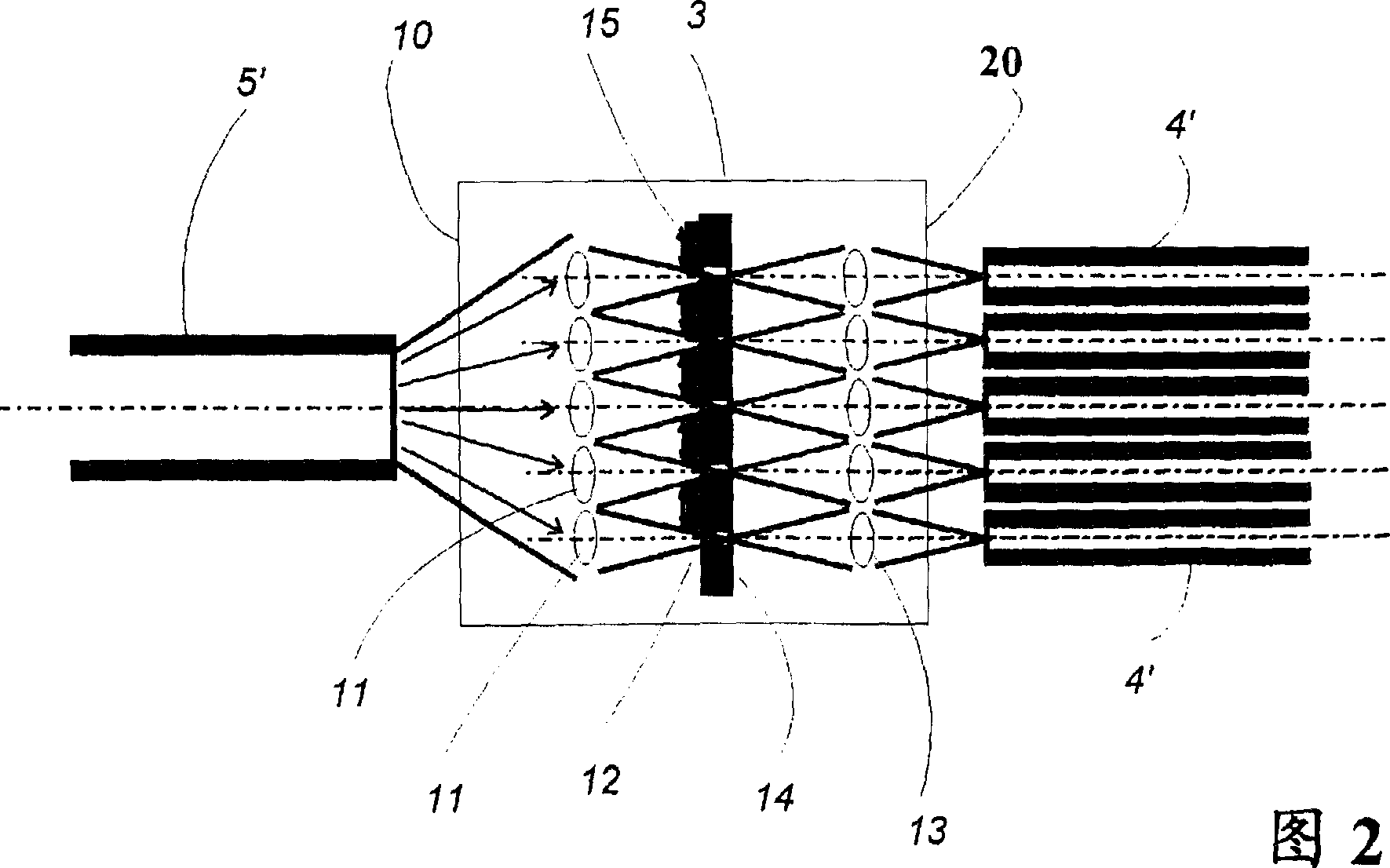
[0095] Figure 2 shows a more specific embodiment of the invention.

[0096] A single optical waveguide 5' guides the light emitted from the light source to the control device 3, from which the light then passes...


PUM


Abstract

The invention relates to a method and a device for controlling the light from a light source (1) to a lighting place. A preferred embodiment of the invention comprises exactly one central light source (1) connected via a control device (3) to a plurality of optical waveguides (4), each terminated at a remote point. The control device includes a plurality of electronically controlled micro-shutters (14, 15), each shutter has at least two states of closed and open, and the light is further guided to the lighting place through the optical waveguide in the open state of the diaphragm. Thus, by means of the control means (3) it is possible to distribute the optical waveguides (4) to individual optical waveguides (4) in response to control signals supplied to the control means.

Description

technical field [0001] The present invention relates to a method and device for controlling light, in particular to a method and device for controlling light from one or more light sources to one or more lighting places. Background technique [0002] With regard to so-called remote source lighting where one or more light sources are separated from the actual location where the light is to be illuminated, it is desirable to efficiently guide light with limited or controlled losses. Various types of optical waveguide technologies are used in this respect and can be adapted to the task proposed according to this requirement. Examples of such applications include endoscopy, display and general lighting purposes. [0003] As light waveguide technology becomes increasingly economically attractive and its possible applications increase accordingly, lightguide optics, especially for some applications such as lighting purposes, have found alternatives to conventional technologies. ...

Claims


Application Information

Patent Timeline
Patent Type & Authority Patents(China)
IPC IPC(8): F21V8/00F21S2/00B60Q1/00G02B6/26G02B6/28G02B6/35G02B6/42
CPCB60Q1/0011G02B6/0006G02B6/264G02B6/266G02B6/2848G02B6/353G02B6/3532G02B6/3548G02B6/3552G02B6/3558G02B6/3594G02B6/4298
Inventor 赫宁·赫宁森
Owner 迪科公司
Why Eureka
Try Eureka