Planetary roller screw transmission mechanism capable of achieving self-adaptive temperature control

A technology of planetary roller and transmission mechanism, applied in the direction of transmission, transmission parts, mechanical equipment, etc., can solve the problems affecting the service life of planetary roller screw transmission mechanism, thermal deformation of planetary roller screw transmission mechanism, Column screw drive mechanism damage and other problems, to achieve the effect of easy installation, good self-adaptation, and lower temperature rise

Inactive Publication Date: 2019-03-22
NORTHWESTERN POLYTECHNICAL UNIV
13 Cites 5 Cited by

AI-Extracted Technical Summary

Problems solved by technology

[0003] The friction of the planetary roller screw transmission mechanism will generate heat during the long-term movement at high speed, which will cause the temperature to rise. If the total heat generated is too much and the heat exchange is insufficient, the viscosity of the grease will be affected, resulting in the ...

Abstract

The invention discloses a planetary roller screw transmission mechanism capable of achieving self-adaptive temperature control. The planetary roller screw transmission mechanism comprises a nut (9). Inner gear rings (10) in rotary butt joint with the nut (9) are arranged at the two ends of the nut (9). An end cover (7) in rotary connection fit with the nut (9) is arranged at one end of the nut (9). Multiple rolling columns (8) arranged in an annular array manner are arranged in the nut (9). Straight teeth are machined at the two ends of each rolling column (8). The straight teeth are engaged with the inner gear rings (10) at the two ends of the nut (9). The rolling columns (8) are circumferentially and evenly distributed around a hollow lead screw (14) through holders (11). By means of a cooling circulating system, cooling liquid flows through the hollow lead screw through a liquid outlet pipe to take away part of heat generated by the lead screw, part of heat generated by the nut is taken away by an end cover wedge hole and a nut annular groove, and temperature increase generated by friction during work of the planetary roller screw transmission mechanism can be effectively reduced.

Application Domain

GearingGear lubrication/cooling

Technology Topic

Self adaptiveRoller screw +4

Image

  • Planetary roller screw transmission mechanism capable of achieving self-adaptive temperature control
  • Planetary roller screw transmission mechanism capable of achieving self-adaptive temperature control
  • Planetary roller screw transmission mechanism capable of achieving self-adaptive temperature control

Examples

  • Experimental program(2)

Example Embodiment

[0019] Example 1
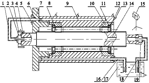
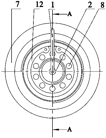
[0020] see Figure 1-4 , this embodiment includes a nut 9, the two ends of the nut 9 are provided with an inner ring gear 10 that is screwed and docked with it, and one end of the nut 9 is provided with an end cover 7 that is screwed and matched with it, and the inside of the nut 9 There are several rollers 8 arranged in a circular array, and the two ends of each roller 8 are processed with straight teeth, which mesh with the inner ring gear 10 installed at both ends of the nut 9, and the rollers 8 pass through the cage 11 The circumference is evenly distributed around the hollow screw 14, the cage 11 is axially positioned by the retaining ring 12, the roller 8 is provided with an external thread that engages with the hollow screw 14 and the nut 9, and the hollow screw 14 is arranged in the middle of the nut 9, and one end of the nut 9 is provided with an end cap 7 screwed to it, and the end of the hollow lead screw 14 passes through the end cap 7 and is connected to the outer ring of the large rotary joint 2 through a key 4 Together, the large rotary joint 2 is a hollow structure connected with the hollow lead screw 14 as a whole, an angle encoder 3 is installed on the outer surface of the large rotary joint 2, and an angle encoder 3 is installed at the end of the large rotary joint 2. The screw 14 is connected to the connecting pipe 1, the end of the connecting pipe 1 is connected with the end cover 7 through the screw 5 and the sealing ring 6, and the middle part of the nut 9 is axially provided with an annular groove 23 and an outlet through hole 24, The end of the annular groove 23 communicates with the end of the outlet through hole 24, and the end of the outlet through hole 24 is equipped with a liquid return pipe 16, and the end of the liquid return pipe 16 is connected with the cooling liquid circulation pump 17 A liquid outlet pipe 18 is installed on one side of the coolant circulation pump 17, and the end of the liquid outlet pipe 18 is connected to the hollow lead screw 14 through a small rotary joint 19.
[0021] A magnetic temperature sensor 13 is installed on the outer surface of the nut 9 and the coolant circulating pump 17 , and a thermal imager 15 is placed on one side of the nut 9 .
[0022] The outer side of the end cover 7 is provided with a thin wall 21 that can be tightly inserted into the annular groove 23. One end of the thin wall 21 communicates with the sealing ring 6 through the end cover 7, and the end of the thin wall 21 is connected to the annular groove 23. The grooves 23 are connected, and the axial section of the thin wall 21 is a wedge-shaped hole with an inclination angle of 10 degrees. The nut 9 forms a wedge-shaped space. Down into the nut annular groove 23, improving the cooling effect of the nut.
[0023] Said nut 9 processes an annular groove 23 of a certain depth from one side, and this annular groove cannot penetrate to the other side of the nut 9 so as to cooperate with the thin wall 21 of the end cover to form a cavity. There is an outlet through hole 24 connected to the annular groove 23 on the far side, and the outlet through hole 24 is connected to the external liquid return pipe 16 .

Example Embodiment

[0024] Example 2
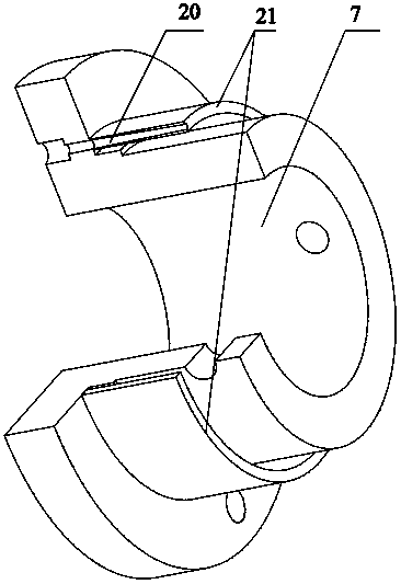
[0025] In this specific embodiment, the coolant circulating pump 17 provides power, and the coolant flows through the outlet pipe 18 through the hollow lead screw 14 to take away part of the heat generated by the lead screw, and then takes it away through the wedge-shaped hole 20 of the end cover and the annular groove 23 of the nut Part of the heat generated by the nut 9 finally flows back to the cooling liquid circulation pump 17 from the outlet through hole 24 below the nut 9 to complete the circulation of the cooling circulation system. Four magnetic temperature sensors 13 are placed on the nut 9 to pass through the magnetic temperature sensor 13 The monitored temperature changes are used to feedback and adjust the flow rate of the coolant circulation pump 17, so that the temperature can be adaptively maintained within a certain range, and when the set temperature upper limit is reached, the program will generate an alarm. And place a thermal imager 15 to monitor the temperature change of the hollow lead screw 14;
[0026] The coolant circulation pump 17 described in this specific embodiment is stepless speed regulation, the speed regulation range is 30rpm ~ 3000rpm, every time the temperature rises by 1°C, the speed increases by 10rpm, every time the temperature drops by 1°C, the speed decreases by 10rpm, the coolant There is a certain capacity of cooling liquid (water or oil) inside the circulating pump 17. When working, the liquid inside the circulating pump 17 will flow out from the liquid outlet pipe 18 at a set flow rate, and finally flow back to the cooling liquid circulating pump through the liquid return pipe 16. In 17, the coolant circulation pump 17 can provide power for the entire cooling circulation system;
[0027] The outer ring of the large rotary joint 2 described in this specific embodiment is connected with the end of the rotating hollow screw 14 through the key 4, the inner ring is connected with the connecting pipe 1 to prevent rotation and can realize the transmission of liquid, the outer ring can be rotation, the inner ring cannot rotate; the circumference of the large rotary joint 2 and the angle encoder 3 are fastened by screws, and the two are integrated to make a rotation movement together, and the angle encoder 3 can measure the rotation angle of the hollow screw 14;
[0028]The magnetic temperature sensor 13 described in this specific embodiment is adsorbed on the nut 9 by magnetic force, and the analog signal collected by the magnetic temperature sensor 13 is converted into a digital signal, which is displayed on the host computer in digital form, and the control module of the host computer Adjust the speed of the coolant circulation pump 17 through feedback control and then adjust its flow rate. The effect of reducing the temperature rise is different due to different coolant flow rates. The upper limit Tmax of the temperature is set in the host computer control software. When the temperature of the magnetic temperature sensor 13 exceeds When the upper limit of the temperature range is set (Temp>Tmax), the speed of the coolant circulation pump 17 increases, the flow velocity of the coolant increases, the more heat is lost, the temperature drops and the temperature is adjusted to reach a steady state (Temp≤Tmax); if the temperature rises If the temperature is too high, the coolant circulation pump 17 has reached the maximum speed but the temperature has not yet dropped to a steady state temperature, the alarm system in the control software will automatically alarm, and then control the planetary roller screw transmission mechanism to stop working, but at the same time it will Make the coolant circulation pump 17 continue to work until the temperature drops to a steady state temperature, the control system can control the planetary roller screw drive mechanism to start working; set four magnetic temperature sensors 13 for parallel control, when one of the temperature sensors 13 When the upper temperature limit is reached, the system will turn on the feedback regulation mode;
[0029] The thermal imager 15 described in this specific embodiment adopts infrared temperature measurement, which can monitor the temperature change of the hollow screw 14 at the part in contact with the external air in real time, and can realize the function of recording data at certain intervals.
[0030] In this specific embodiment, the connecting pipe 1, the end cover 7 and the large rotary joint 2 are fastened by screws, and a sealing ring 6 is installed at the contact to prevent the coolant from overflowing;
[0031] There is a thin wall 21 on the outside of the end cover 7, and the thickness of the thin wall 21 is just the same as the thickness of the annular groove of the nut. The end cover 7 and the nut thin wall 21 cooperate to form a closed cavity, and the thin wall 21 can also play a role. The role of supporting the nut 9 and enhancing the strength of the nut; there is a wedge-shaped hole 20 at the oil inlet of the end cover 7, and the size of the hole gradually decreases from the oil inlet to the oil outlet of the end cover 7. From the axial section Seeing that it is a wedge-shaped hole with an inclination angle of 10 degrees, the nut 9 forms a wedge-shaped space. The cooling liquid flows in from the large mouth in the end cover 7, flows out from the small mouth, and enters the nut annular groove 23 under pressure, which improves the heat dissipation of the nut. Effect;
[0032] Said nut 9 processes an annular groove 23 of a certain depth from one side, and this annular groove cannot penetrate to the other side of the nut 9 so as to cooperate with the thin wall 21 of the end cover to form a cavity. There is an outlet through hole 24 connecting the annular groove 23 on the far side, and the outlet through hole 24 is connected to the external liquid return pipe 16, so that the cooling liquid flows through the annular groove 23 on the nut 9 after passing through the wedge-shaped hole 20 of the end cover, and is passed through the outlet below the nut. The hole 24 flows out, and finally flows back to the cooling liquid circulation pump 17 through the liquid return pipe 16 .

PUM

no PUM

Description & Claims & Application Information

We can also present the details of the Description, Claims and Application information to help users get a comprehensive understanding of the technical details of the patent, such as background art, summary of invention, brief description of drawings, description of embodiments, and other original content. On the other hand, users can also determine the specific scope of protection of the technology through the list of claims; as well as understand the changes in the life cycle of the technology with the presentation of the patent timeline. Login to view more.

Similar technology patents

Dual-channel cooling device for semiconductor laser

PendingCN114221214AImprove heat dissipation and cooling efficiencyReduce temperature rise
Owner:山东宝鑫达电子科技有限公司

Combined electric welding and power generating dual-purpose machine

InactiveCN104348298AEasy to disassemble for maintenance or replacementReduce temperature rise
Owner:刘方涛 +2

Household single-phase series excitation stirrer motor

InactiveCN106230192Aspark improvementReduce temperature rise
Owner:浙江美茵电机有限公司

Synchronous permanent magnet coupler with single permanent magnet rotor

PendingCN111106735Areduce eddy currentReduce temperature rise
Owner:CCTEG SHENYANG RES INST

Classification and recommendation of technical efficacy words

  • Reduce temperature rise
  • increase contact area

Liquid crystal display device

ActiveCN1716041Areduce temperature riseSuppresses reduction in luminous efficiency
Owner:KYOCERA CORP

Permanent magnet type generator

ActiveUS20060066172A1reduce temperature rise
Owner:DENSO CORP +1

Drawer-type microwave oven

Owner:GUANGDONG MIDEA KITCHEN APPLIANCES MFG CO LTD +1

System For Delivering Warmed Fluids

InactiveUS20070295826A1high flow ratereduce temperature rise
Owner:CANETIS TECH LTD

Rack Robot

ActiveUS20130151004A1reduce temperature rise
Owner:HAMILTON STORAGE TECH

Blood vessel interventional operation conduit or guide wire control device based on two-point clamping

ActiveCN103157170Aincrease contact areaIncrease the upper limit of friction
Owner:北京中科鸿泰医疗科技有限公司

Continuous feeding device for electric arc furnace preheated by flue gases

InactiveCN103075881AImprove mechanical efficiencyincrease contact area
Owner:CISDI ENG CO LTD
Why Eureka
Try Eureka