Valve seat sealing mechanism applicable to low temperature working conditions

A sealing mechanism and valve seat technology, which is applied to the valve shell structure, valve details, valve device, etc., can solve the problem of reduced interference between the lip seal ring, the valve seat and the valve body, hardening of the material, and ineffectiveness. Sealing and other issues, to achieve the effect of high energy utilization, easy manufacture, and compact structure

Pending Publication Date: 2019-03-22
CHAODA VALVE GRP
View PDF0 Cites 1 Cited by
  • Summary
  • Abstract
  • Description
  • Claims
  • Application Information

AI Technical Summary

Problems solved by technology

[0003] At present, conventional ball valves usually use rubber O-rings to seal the valve seat and valve body, but the rubber O-rings will crack or lose elasticity at low temperatures and cannot be effectively sealed.
Therefore, the O-ring can not be used for sealing between the valve seat and the valve body of the cryogenic fixed ball valve, but the lip sealing ring is used for sealing. Support, but the lip of the lip seal ring shrinks greatly at low temperature. At this time, the interference between the lip seal ring, the valve seat and the valve body matching surface will be greatly reduced, and it is difficult to ensure that the lip seal ring reliable sealing of
In addition, the elasticity of ...

Method used


Image

  • Valve seat sealing mechanism applicable to low temperature working conditions
  • Valve seat sealing mechanism applicable to low temperature working conditions
  • Valve seat sealing mechanism applicable to low temperature working conditions

Examples


Embodiment Construction

[0029] In order to make the technical solution of the present invention clearer, the present invention will be further described in detail below in conjunction with the accompanying drawings and embodiments. It should be understood that the specific embodiments described here are only used to explain the present invention, not to limit the present invention.

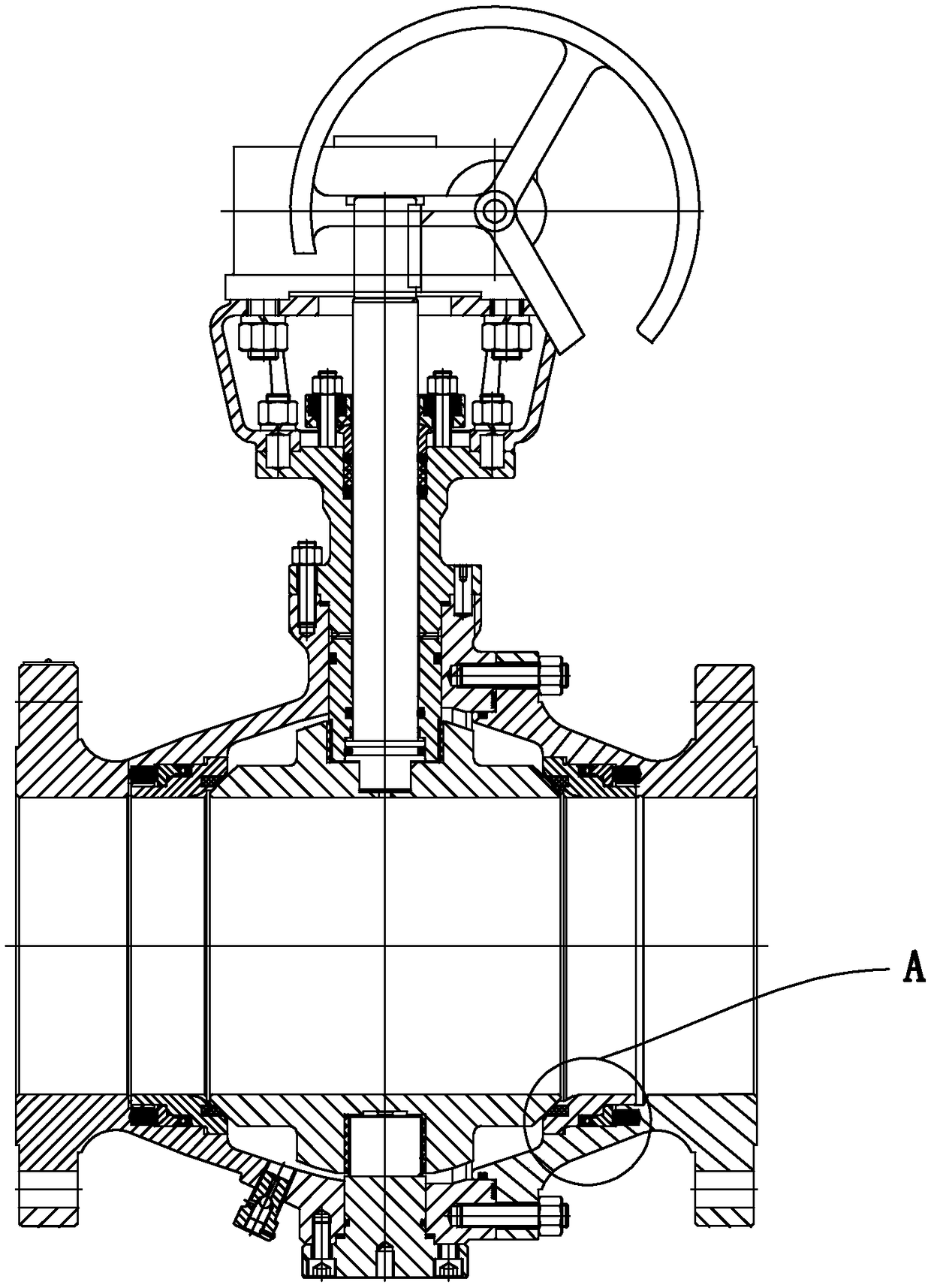
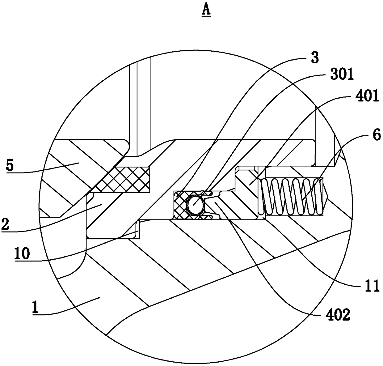
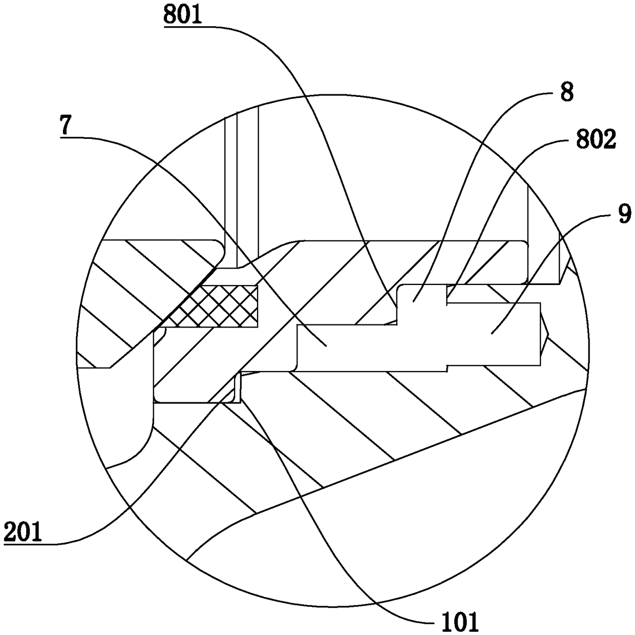
[0030] refer to Figure 1 to Figure 3 , the present invention provides a valve seat 2 sealing mechanism suitable for low temperature working conditions, including a valve body 1 and a ball 5 installed in the valve body 1, and a valve seat 2 sealingly fitted with the ball 5 is also installed in the valve body 1, A sealing ring installation cavity 7 is arranged between the valve seat 2 and the valve body 1, and a lip sealing ring 3 is arranged in the sealing ring installation cavity 7, and the lip sealing ring 3 is connected to the valve seat 2 and the valve body 1. Fittingly, a supporting spring ring 301 is provided betw...


PUM


Abstract

The invention discloses a valve seat sealing mechanism applicable to low temperature working conditions. A lip seal ring is arranged between a valve seat and a valve body; a support spring ring is arranged between two lips of the lip seal ring; a pressing ring is further arranged between the valve body and the valve seat; a pretensioned spring is arranged between the pressing ring and the valve body; and the pretensioned spring drives the pressing ring to abut against the valve seat and the support spring ring. The valve seat sealing mechanism has the beneficial effects that on the one hand, the valve seat can be closely attached to a ball body, so that the ball body and the valve seat have good sealing performance, and on the other hand, acting force is applied to the support spring ringthrough the pressing ring, and the lip seal ring is deformed by compression of the support spring ring, the lips are opened, so that the lip seal ring is attached to the valve body and the valve seatmore closely, even at a very low temperature, the lips of the lip seal ring are contracted to a certain extent, reliable sealing of the lip seal ring can still be ensured, and the better sealing between the valve seat and the valve body is achieved.

Description

technical field [0001] The invention relates to the field of valves, in particular to a valve seat sealing mechanism which adopts a lip sealing ring and is suitable for low-temperature working conditions. Background technique [0002] As a cut-off valve for pipeline systems, ball valves are widely used in various industrial fields such as petroleum, chemical industry, electric power, and urban construction. They have the advantages of small fluid resistance, good sealing performance, and rapid switching. During use, the ball of the ball valve does not move, but only rotates, and the ball can be rotated 90° to open or close the pipeline. The sphere of the fixed ball valve is generally supported by the upper and lower support shafts or support plates. By applying the spring force behind the valve seat and the medium force in the pipeline, the valve seat can be tightly attached to the sphere, so as to achieve the reliability of the sealing surface of the valve seat. seal. [...

Claims


Application Information

Patent Timeline
IPC IPC(8): F16K5/20F16K27/06
CPCF16K5/201F16K27/067
Inventor 邱晓来叶建伟黄明金潘建瓯王汉洲
Owner CHAODA VALVE GRP
Why Eureka
Try Eureka