
Adaptive illumination optimizing method adapting to complicated illumination scene

An optimization method and adaptive technology, applied in the field of adaptive optics, can solve problems such as loss of photo details, and achieve the effect of strong repeatability, simple algorithm and low equipment requirements

Inactive Publication Date: 2019-03-22
TIANJIN UNIV
View PDF5 Cites 8 Cited by
  • Summary
  • Abstract
  • Description
  • Claims
  • Application Information

AI Technical Summary

Problems solved by technology

[0003] Aiming at the problem of loss of photo details in complex lighting scenes, the present invention proposes an optimized adaptive lighting scheme to realize lighting compensation and further processing

Method used


Image

  • Adaptive illumination optimizing method adapting to complicated illumination scene
  • Adaptive illumination optimizing method adapting to complicated illumination scene
  • Adaptive illumination optimizing method adapting to complicated illumination scene

Examples


Embodiment Construction

[0021] The present invention will be further described below in conjunction with the accompanying drawings and specific examples.

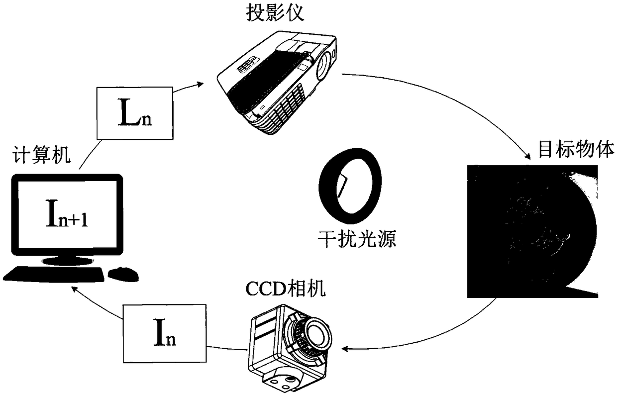
[0022] see figure 1 , a schematic diagram of the device of the present invention: the image acquisition adopts a high-definition 1.2 million-pixel CCD camera, the projection equipment adopts EPSON's CB-S18+ projector, the object to be measured adopts an iron cover with a two-dimensional code label, and the processor is any PC or has The PC function equipment, the projector projects the stripes and the iterative image, the CCD camera collects the image of the object after adaptive projection, and the MATLAB program operates the iterative algorithm. The system setup of this experiment refers to the projector-camera system.

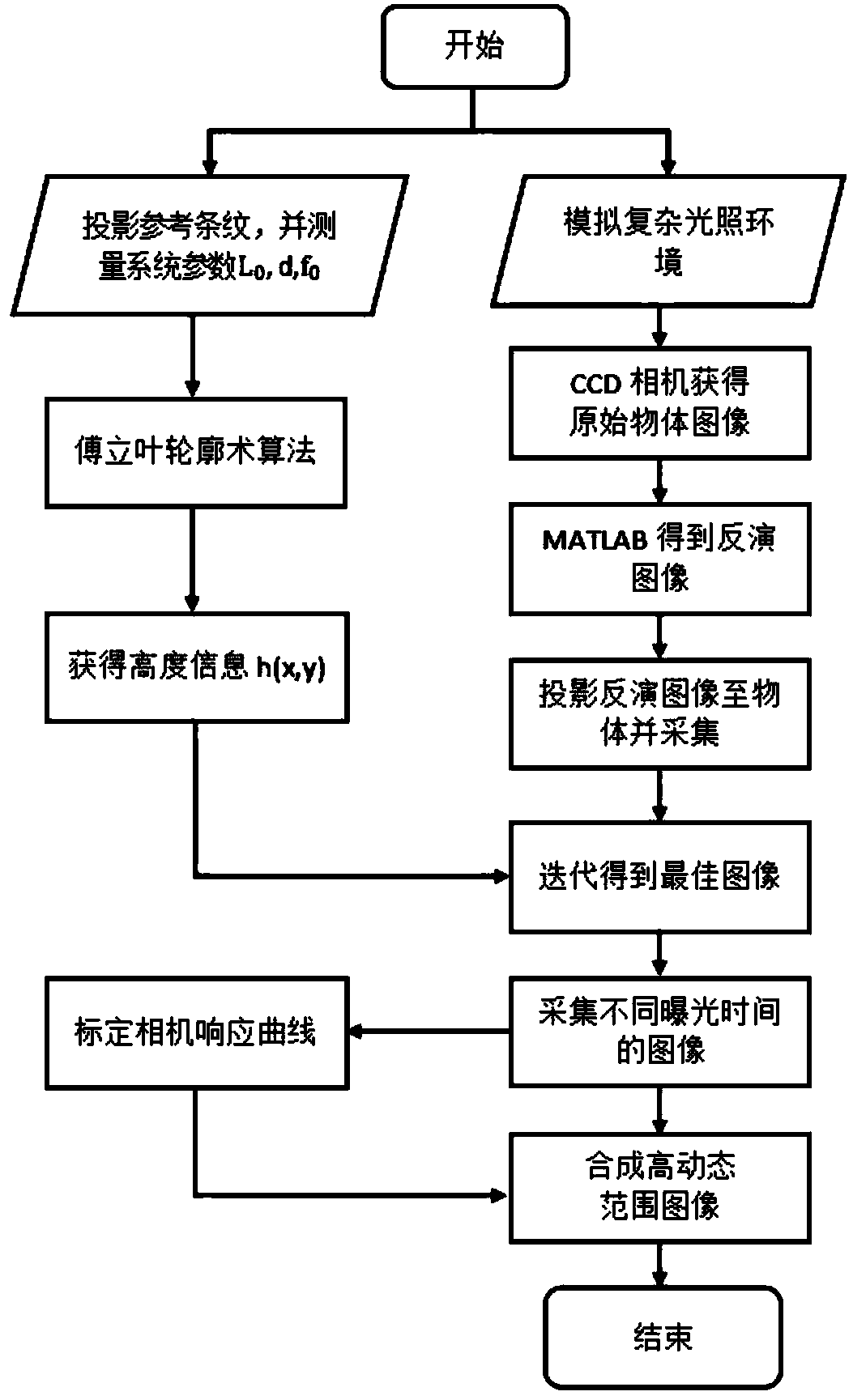
[0023] see figure 2 , the flow chart of the self-adaptive projection method based on exposure compensation in the present invention, the corresponding steps are briefly described below:

[0024] (1) Place the equipment so th...


PUM


Abstract

The invention relates to an adaptive illumination optimizing method adapting to a complicated illumination scene. The adaptive illumination optimizing method adapting to the complicated illumination scene comprises the following steps: establishing a projector-camera system; simulating a complicated illumination environment, selecting measured objects with different surface reflectance to preventoverexposure of an interference light source, and controlling a CCD camera by a computer to obtain an original object image; projecting reference stripes generated by the computer to an object througha projector, selecting black and white stripes of which the phase difference is between 0 and 2 pi as the reference stripes which can distort after the strips are deeply modulated by a three-dimensional object, and acquiring the distorted strips by a camera; recovering the height information of the object; carrying out inverse operation on the original object image, and projecting an inverse image to the surface of the object by a projector and keeping pixel matching; running an iterative algorithm until an iterative termination criterion is met to ensure that an overexposure portion is partially repaired; calibrating a camera response curve; and fitting a high-dynamic range image, namely a HDR image, according to the camera response curve, and obtaining and outputting a final result.

Description

technical field [0001] The invention relates to a method for optimizing adaptive lighting, which belongs to the field of adaptive optics. Background technique [0002] In current machine vision systems, image quality is the decisive factor for system analysis and decision-making. Due to the complex environment, different surface reflectance of objects, uneven light source and other factors, the details of the image are usually lost. When there are different parts with high reflectivity and low reflectivity in the scene under test, increasing the exposure will oversaturate the part with high reflectivity; reducing the exposure will make the part with low reflectivity dark, thereby degrading the image quality and causing damage to the system Negative Effects. Contents of the invention [0003] Aiming at the problem of loss of photo details in complex lighting scenes, the present invention proposes an optimized adaptive lighting scheme to realize lighting compensation and f...

Claims


Application Information

Patent Timeline
Patent Type & Authority Applications(China)
IPC IPC(8): G01B11/25G06T5/00
CPCG01B11/254G06T5/90
Inventor 吕辰刚白杨苌雨晴
Owner TIANJIN UNIV
Learn More