
Non-contact detecting method and device for curved-surface prism

A technology of a curved prism and a detection method, which is applied in the field of optical detection, can solve the problems of complex test optical path, low test accuracy, inability to realize quantitative detection, etc., and achieves the effects of high test accuracy and simple detection process.

Active Publication Date: 2019-03-22
XI'AN INST OF OPTICS & FINE MECHANICS - CHINESE ACAD OF SCI
View PDF6 Cites 0 Cited by
  • Summary
  • Abstract
  • Description
  • Claims
  • Application Information

AI Technical Summary

Problems solved by technology

[0007] The purpose of the present invention is to overcome the shortcomings of existing curved prism contact detection methods that easily damage the prism optical surface and low test accuracy; the non-contact detection method has complex testing optical paths and cannot achieve quantitative detection, and provides a curved prism non-contact detection method and device; the detection device and method are non-contact detection, do not damage optical parts, can meet the fast, non-destructive and high-precision detection requirements of the curved prism to be tested, and can be used for optical processing and assembly of the curved prism to be tested

Method used


Image

  • Non-contact detecting method and device for curved-surface prism

Examples


Embodiment Construction

[0029] The present invention will be further described in detail below in conjunction with the accompanying drawings and embodiments.

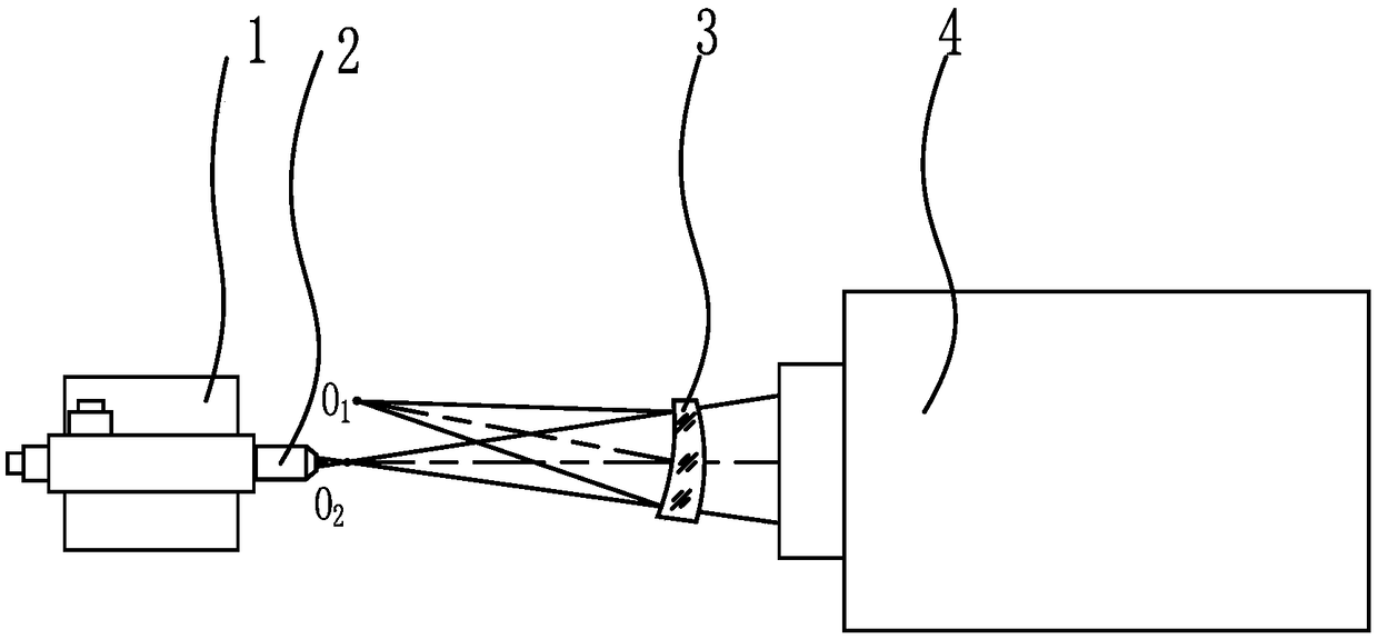
[0030] Such as figure 1 As shown, the present embodiment provides a curved prism non-contact detection device for detecting a curved prism 3 to be measured; the curved prism concave radius R 1 =169mm, caliber D 1 =Φ70mm, convex radius R 2 =186mm, caliber D 2 =Φ72mm, the distance between the center of the sphere is Δ=17.5mm, and the numerical aperture of the concave surface is D 1 / 2R 1 ≈0.21, the F-number of the convex surface is R 2 / D 2 ≈2.58.

[0031] The detection device comprises an optical platform (not shown in the figure), an autocollimating microscope 2 and a spherical interferometer 4 arranged on the optical platform; A space for placing the curved prism 3 to be measured is reserved between the microscope 2 and the spherical interferometer 4 ; the autocollimating microscope 2 is installed on the optical platform through the p...


PUM


Abstract

The invention relates to the technical field of optical detection, and provides a non-contact detecting method and device for a curved-surface prism for solving the problems that an existing contact detecting method for a curved-surface prism easily damages the optical surface of the prism and is low in testing precision; and an existing non-contact detecting method is complicated in testing optical path, quantitative detection cannot be realized and the like. The detecting method comprises the following steps: 1) aligning an auto-collimation microscope with a sphericity interferometer; 2) placing a to-be-detected curved-surface prism between the auto-collimation microscope and the sphericity interferometer, and enabling the convex surface of the to-be-detected curved-surface prism to be positioned in front of the sphericity interferometer; and 3) detecting the convex surface of the to-be-detected curved-surface prism by the sphericity interferometer, and adjusting the to-be-detected curved-surface prism to realize auto-collimation of the convex surface of the to-be-detected curved-surface prism and a light beam of the sphericity interferometer; and then detecting the concave surface of the to-be-detected curved-surface prism by the auto-collimation microscope, and moving the auto-collimation microscope to realize auto-collimation between the auto-collimation microscope and theto-be-detected curved-surface prism. The relative movement amount of the auto-collimation microscope is the distance of the center of sphere of the to-be-detected curved-surface prism.

Description

technical field [0001] The invention relates to the technical field of optical detection, in particular to a non-contact detection method and device of a curved prism. Background technique [0002] In 1911, Féry.C.H proposed the curved prism or Ferry prism (Féry prism) based on the principle of Rowland circle. and imaging capabilities. When the curved prism is used as a spectroscopic element in a spectroscopic system, the structure of the system can be greatly simplified and the quality of the system can be reduced. [0003] However, the curved prism is a non-rotationally symmetrical part, with one side being concave and the other being convex. The distance between the two surfaces of the curved prism to be tested, that is, the inclination angle or the off-axis value, has very high requirements. The traditional method of inspecting flat prisms or lenses cannot complete the inspection, which brings many difficulties to its processing and adjustment. [0004] Aiming at the ...

Claims


Application Information

Patent Timeline
Patent Type & Authority Applications(China)
IPC IPC(8): G01M11/02
CPCG01M11/0228
Inventor 李立波赵强孙丽军丑小权武俊强付西红
Owner XI'AN INST OF OPTICS & FINE MECHANICS - CHINESE ACAD OF SCI
Learn More