Sky wheel type steel wire rope ring automatic welding device

An automatic welding, Ferris wheel type technology, applied in auxiliary devices, welding equipment, auxiliary welding equipment and other directions, can solve the problems of inability to adapt to large-scale production, limited number of wire rope loops, and incompatibility with robot operation, etc., to improve quality and Ease of operation, good welding quality, good roundness

Pending Publication Date: 2019-03-26
HUBEI UNIV OF AUTOMOTIVE TECH
View PDF1 Cites 0 Cited by
  • Summary
  • Abstract
  • Description
  • Claims
  • Application Information

AI Technical Summary

Problems solved by technology

However, the number of wire rope loops to be processed on the tooling of this structure is limited. At the same time, the steel wire rope loops to be processed are clamped in the annular groove of the wire rope loop positioning block, which is not suitable for manipulators to operate, and the steel wire rope loops need to be clamped by the block. One has to be disassembled once, which is extremely inconvenient to operate, resulting in low production efficiency and unable to meet the needs of large-scale production

Method used


Image

  • Sky wheel type steel wire rope ring automatic welding device
  • Sky wheel type steel wire rope ring automatic welding device
  • Sky wheel type steel wire rope ring automatic welding device

Examples


Embodiment 1

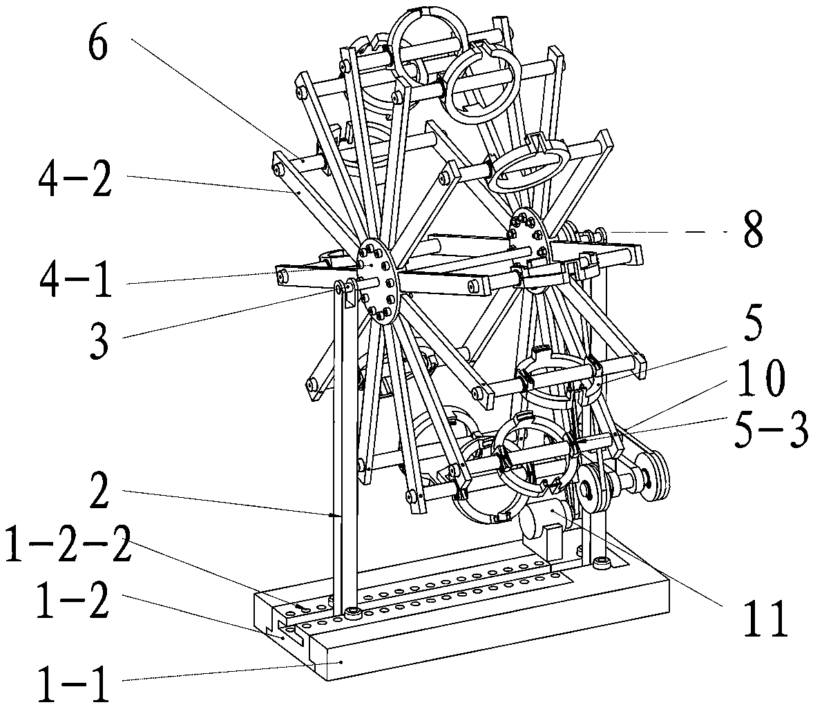
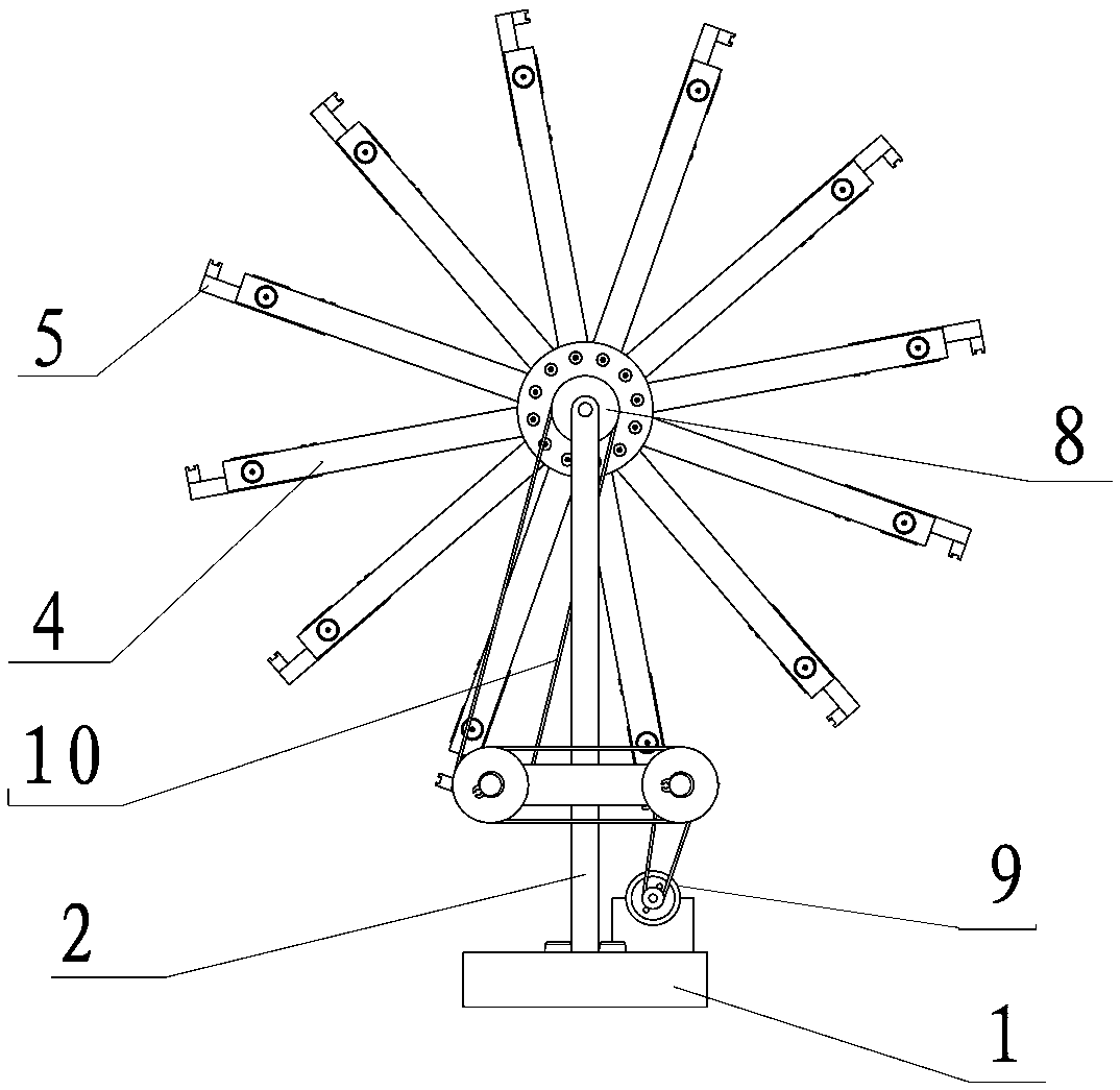
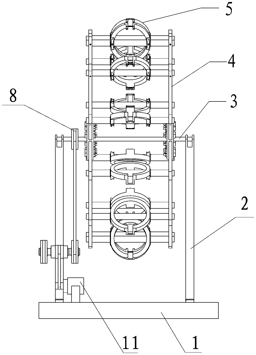
[0042] A specific structure of the wire rope ring positioning fixture 5 is as follows: comprising an annular base 5-1, the annular base 5-1 is radially pierced on the fixed shaft 6 and fixed by a screw and the shaft with a circlip, the annular base 5 -1 is fixed with a plurality of spaced positioning projections 5-2 by bolts, the top of the positioning projections is provided with a groove 5-3 that matches the arc of the wire rope ring, and a plurality of spaced grooves 5-3 form an annular The outline constitutes the positioning groove of the steel wire rope ring, and the groove at the top of one of the positioning projections 5-2 is the welding part of the steel wire rope ring joint, and the welding part extends downwards along the groove 5-3 to be provided with an empty slot.

Embodiment 2

[0044] The difference from Embodiment 1 is that a transitional connection block 7 is added, and the transitional connection block 7 is fixed on the fixed shaft 6 by screws and a shaft circlip, and then the ring base 5-1 is fixed on the transitional connection block by screws 7, other installation structures on the annular base 5-1 are the same as in Embodiment 1, so that it is convenient to disassemble and replace the wire rope ring positioning fixture 5.

Embodiment 3

[0046] On the basis of Embodiment 1, an upwardly extending protrusion 12 is added between the spaced positioning protrusions 5-2 on the annular base 5-1, and the end of the protrusion is radially inward or Outward extension is provided with the wire rope loop processing part 13 that adapts to other models, is provided with the height difference that avoids mutual interference between this processing part and the spaced positioning projection 5-2, is provided with the steel wire rope ring of this type on this processing part. The groove 2 14 adapted to the circular arc, the annular contour formed by a plurality of spaced grooves 14 constitutes the second wire rope ring positioning groove on the tooling, and the groove 2 14 on one of the raised parts is the welding part of the wire rope ring joint , the welding part extends downward along the groove 2 14 and is provided with an empty slot; the additional structure of this part is a separate integral part, which is detachably moun...


PUM


Abstract

The invention discloses a sky wheel type steel wire rope ring automatic welding device which comprises a base, supporting rods, a rotating shaft, a wheel body and a steel wire rope ring locating lamp.The supporting rods are fixed to the two sides of the base. The two ends of the rotating shaft are installed at the upper ends of the supporting rods correspondingly. The wheel body is installed on the rotating shaft in a sleeving manner. A rotating shaft drive installing portion is arranged on the portion, located between the wheel body and the rotating shaft installing base, of one side of therotating shaft. The wheel body comprises symmetrical discs, and disc connecting rods which are uniformly arranged along the circumference face of each disc in a radial structure. Installing holes areformed in the end portions of the disc connecting rods. A fixing shaft used for fixing the steel wire rope ring locating clamp is connected between the opposite connecting rods on the two discs through the installing holes in the end portions of the connecting rods. The steel wire rope ring locating clamp is installed on the fixing shaft and provided with a steel wire rope ring locating groove. According to the automatic welding device, 360-degree all-position welding of a steel wire rope ring connector is achieved by the adoption of a mechanical hand, the assembling and disassembling link isreduced, the welding quality and convenience are improved, the production efficiency is improved, and the automatic welding device is suitable for needs of mass production.

Description

technical field [0001] The invention relates to the field of welding and processing of steel wire rings, in particular to a ferris wheel-type automatic welding device for steel wire rings, which is especially suitable for welding circular elastic elements in various vibration isolators, shaft couplings, and vibration damping and buffering equipment. processing. Background technique [0002] The wire rope ring has good hysteretic nonlinear characteristics, strong vibration absorption capacity, and large static and dynamic deformation capabilities. It has been widely used as an elastic element in dry friction damping hysteresis vibration isolation such as wire rope ring vibration isolators and wire rope ring couplings. device field. As the elastic damping elements, the steel wire loops are independent and isolated from each other, and are used to change the elasticity and damping characteristics of the vibration isolation device. It has the characteristics of convenient clam...

Claims


Application Information

Patent Timeline
IPC IPC(8): B23K37/047
CPCB23K37/047
Inventor 王红霞罗豹陈大顶郑诚诚戢玉莹汪睿
Owner HUBEI UNIV OF AUTOMOTIVE TECH
Why Eureka
Try Eureka