A casting mold for anti-swirl nozzle

A technology for casting molds and spouts, which is applied in the direction of molds, manufacturing tools, mold auxiliary parts, etc., and can solve problems such as critical personal safety, wasting time, and affecting production efficiency

Active Publication Date: 2021-06-15
SHANGHAI LIER REFRACTORY MATERIAL +1
View PDF0 Cites 0 Cited by
  • Summary
  • Abstract
  • Description
  • Claims
  • Application Information

AI Technical Summary

Problems solved by technology

Zirconia upper nozzle products are usually pressed by hand-moving molds, which are heavy and seriously affect production efficiency. Once the mold cracks during use, it will endanger personal safety
The production efficiency of small zirconia products is not high by manual methods, and it is time-consuming to repeatedly operate for loading, pressing, and demolding

Method used


Image

  • A casting mold for anti-swirl nozzle
  • A casting mold for anti-swirl nozzle

Examples


Embodiment 1

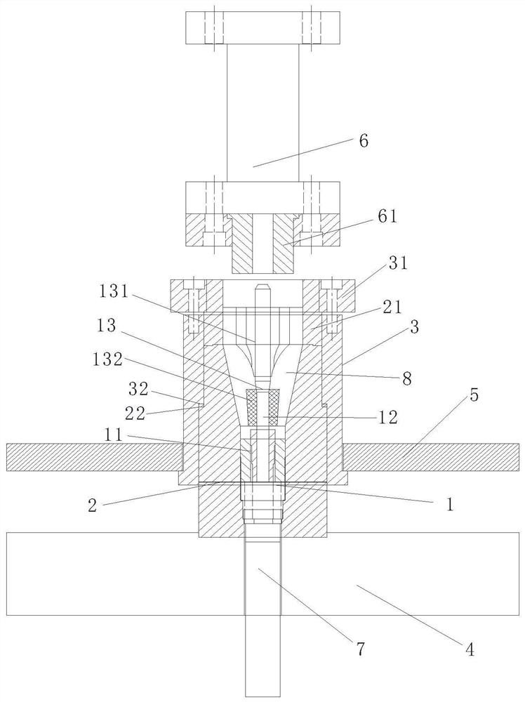
[0025] like figure 1 As shown, an anti-swirl nozzle casting mold, the anti-swirl nozzle casting mold includes a mold body 1, a main mold cover 2, a protective cover 3, a base 4, a floating platform 5 that can move up and down, a main cylinder 6 and a top Cylinder 7, the main mold sleeve 2 is socketed outside the mold body 1, and a material layer 8 is formed between the two, and the protective sleeve 3 is sleeved outside the main mold sleeve 2 and fixed with the floating platform 5 Connected, the bottom of the main mold cover 2 is fixedly connected with the base 4, the lower end of the mold body 1 is connected with the jack cylinder 7, and its upper end is movably connected with the main cylinder 6.

[0026] In practical application, the mold body 1 includes a core base 11, a core rod 12 and a core 13, the bottom of the core rod 12 is movably connected to the core base 11, and the core base 11 is connected to the core base 13. The jack cylinder 7 is connected, and the mold cor...

Embodiment 2

[0034] A method for casting an anti-swirl nozzle, the method for casting an anti-swirl nozzle comprises the following steps:

[0035] Step S1: Proportioning raw materials and binders and granulating to obtain the required casting materials;

[0036] Specifically, it can be: mix raw materials such as corundum, quartz, graphite, alumina micropowder, etc., according to the required weight percentage, to provide preparation for the next step of granulation;

[0037] A binder is added to the powder obtained after proportioning, and granulated to meet the conditions of the required casting material in the mold molding operation. Preferably, the binder in this embodiment is phenolic resin. The casting material is in the form of mud.

[0038] Step S2: Fix the main mold cover on the base, and fix the protective cover on the floating platform;

[0039] Step S3: After splicing and forming the main body of the mold, it is connected and fixed with the top cylinder in the middle of the ma...


PUM


Abstract

The invention discloses an anti-swirl nozzle casting mold, which comprises a mold main body, a main mold cover, a protective cover, a base, a floating platform capable of moving up and down, a main cylinder and a top cylinder, and the main mold cover is sleeved on the mold main body In addition, a material layer is formed between the two, the protective sleeve is sleeved outside the main mold sleeve and fixedly connected with the floating platform, the bottom of the main mold sleeve is fixedly connected with the base, and the lower end of the mold body is connected to the base. The top cylinder is connected, and its upper end cooperates with the main cylinder; the main mold sleeve of the mold is fixed on the base of the hydraulic press, and the semi-automatic production of the zirconia upper nozzle is realized through the cooperation of the main cylinder and the top cylinder, which greatly improves the production efficiency , to achieve single-person operation and reduce labor intensity; because there is a protective cover outside the main body of the mold, the safety factor of the mold is greatly improved; when demolding, the product is pressed out of the mold through the upward movement of the platform and the main body of the mold to achieve rapid prototyping, which fully meets the single-person operation demand.

Description

technical field [0001] The invention relates to the technical field of refractory molds, in particular to an anti-swirl nozzle casting mold. Background technique [0002] The existing zirconia upper nozzle products have problems such as uneven product density, large shrinkage and deformation during firing, high reject rate, and low molding efficiency. Because the mold is bulky, more than 2 people are often required to operate it. Zirconia upper nozzle products are usually pressed by hand-moving molds, which are heavy and seriously affect production efficiency. Once the mold is cracked during use, it will endanger personal safety. The production efficiency of small zirconia products is not high by manual method, and the repeated operations of loading, pressing and demolding are very time-consuming. Contents of the invention [0003] In view of the above-mentioned shortcomings existing at present, the present invention provides an anti-swirl nozzle casting mold, which can ...

Claims


Application Information

Patent Timeline
Patent Type & Authority Patents(China)
IPC IPC(8): B28B7/00B28B7/30
CPCB28B7/0002B28B7/0097B28B7/30
Inventor 李洪波侯金玉汪正峰颜浩邹新国
Owner SHANGHAI LIER REFRACTORY MATERIAL
Why Eureka
Try Eureka