Yarn scraping device for spun bobbin and control method thereof

A spun bobbin and No. 1 technology, applied in the spinning bobbin scraping device and its control field, can solve the problems of high labor intensity and poor cleaning effect of residual yarn, achieve good cleaning effect of residual yarn and improve yarn scraping effect , the effect of reducing labor intensity

Active Publication Date: 2020-06-26
HUBEI TIANMEN TEXTILE MACHINERY
View PDF7 Cites 0 Cited by
  • Summary
  • Abstract
  • Description
  • Claims
  • Application Information

AI Technical Summary

Problems solved by technology

[0003] The purpose of the present invention is to overcome the defects and problems existing in the prior art that the residual yarn cleaning labor intensity is high and the residual yarn cleaning effect is poor, and to provide a spun bobbin scraping device with low labor intensity and good residual yarn cleaning effect and its control method

Method used


Image

  • Yarn scraping device for spun bobbin and control method thereof
  • Yarn scraping device for spun bobbin and control method thereof
  • Yarn scraping device for spun bobbin and control method thereof

Examples


Embodiment 1

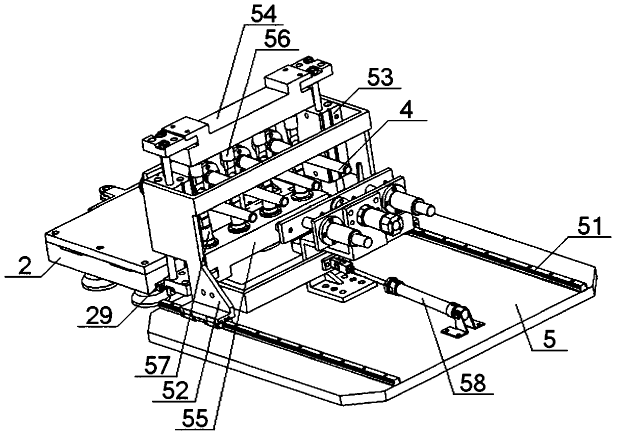
[0058] see Figure 1 to Figure 8 , a spun bobbin yarn scraping device, comprising a circular guide rail 1 and a conveying trolley 2 slidably connected thereon, a timing belt 3 is arranged on the inner side of the circular guide rail 1, the synchronous belt 3 is connected with the conveying trolley 2, and the conveying trolley 2 is horizontally provided with a plurality of sleeves 21 for fitting the spun bobbin 4, and the outer side of the annular guide rail 1 is located near the conveying trolley 2 and is provided with an installation base plate 5, and two guide rails 51 are arranged in parallel on the installation base plate 5, Two guide rails 51 are slidably connected with a No. support 52, and two bidirectional cylinders 53 are vertically and symmetrically arranged on the No. 1 support 52, and one end of the two bidirectional cylinders 53 is vertically connected with a No. One end is vertically connected with No. 2 plate 55, and the No. 1 plate 54 is located on the end face...

Embodiment 2

[0061] Basic content is the same as embodiment 1, the difference is:

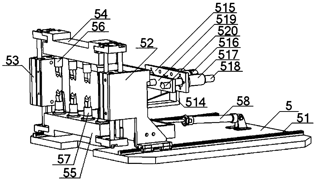
[0062] see figure 2 , No. 2 bracket 514 is set on the installation bottom plate 5, No. 1 installation plate 515 and No. 2 cylinder 516 are arranged on No. 2 bracket 514, linear bearing 517 is arranged on No. 1 installation plate 515, and guide Rod 518, guide rod 518 is connected with No. 2 mounting plate 519, is provided with a plurality of top cones 520 on No. 2 mounting plate 519, and the output end of described No. 2 cylinder 516 passes through No. 2 bracket 514, No. 1 mounting plate successively After 515, it is connected with No. 2 mounting plate 519.

[0063] After the No. 1 bracket 52 stops moving, control the No. 2 cylinder 516 to extend, and the No. 2 cylinder 516 drives the No. 2 mounting plate 519 to move in the direction of the spinning bobbin 4 until the top cone 520 tightens the spinning bobbin 4 behind the No. 2 mounting plate 519 stops moving.

Embodiment 3

[0065] Basic content is the same as embodiment 1, the difference is:

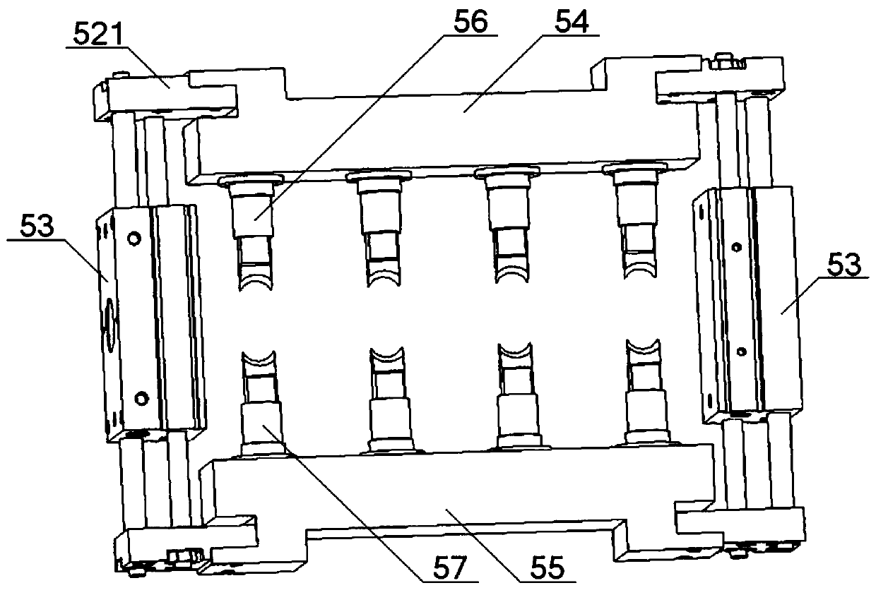
[0066] see Figure 1 to Figure 5 The No. 1 yarn scraping knife 56 and the No. 2 yarn scraping knife 57 all include a base 59, a knife case 510, and a cutter head 511. One end of the knife case 510 is set on the base 59, and the other end of the knife case 510 is set on the On one end of the cutter head 511, the other end of the cutter head 511 is provided with a semicircular groove 512, and a spring 513 is arranged in the described cutter housing 510, and one end of the spring 513 is in contact with the base 59, and the other end of the spring 513 is in contact with the cutter head 511. contact, the cutter head 511 can move along the inner wall of the cutter housing 510 .


PUM


Abstract

The invention provides a ring bobbin yarn scraping device. The ring bobbin yarn scraping device comprises an annular guide rail and a conveying trolley slidably connected to the annular guide rail. The conveying trolley is horizontally provided with a plurality of ring bobbins. A mounting base plate is arranged on the outer side of the annular guide rail. A first support is slidably connected to the mounting base plate. The first support is connected with a cylinder. Two-way cylinders are arranged on the first support. The two ends of each two-way cylinder are connected with a first plate anda second plate. First yarn scraping knives and second yarn scraping knives are connected to the first plate and the second plate correspondingly. The first yarn scraping knives and the second yarn scraping knives are symmetrically arranged on the two sides of the ring bobbins. The first yarn scraping knives and the second yarn scraping knives each comprise a base, a knife shell and a knife head which are connected in sequence in a sleeved mode. The end of each knife head is provided with a semicircular groove. A spring is arranged in each knife shell. A second support is arranged on the mounting base plate. A mounting plate and cylinders which are connected are arranged on the second support. Tip cones are arranged on the mounting plate. The ring bobbin yarn scraping device is small in labor intensity of residual yarn cleaning, good in residual yarn cleaning effect, wide in application range and low in ring bobbin scrap rate.

Description

technical field [0001] The invention relates to the field of textile technology, in particular to a yarn scraping device for a spun bobbin and a control method thereof, which are mainly suitable for reducing the labor intensity of residual yarn cleaning and improving the residual yarn cleaning effect. Background technique [0002] The yarn is wound on the surface of the bobbin for the weaving and production process of spinning. Generally, when there is a small amount of yarn residue on the surface of the bobbin, the worker will replace the bobbin. In order to ensure the repeated use of the spun bobbin, it is necessary to manually remove the remaining yarn on the surface. Due to the huge amount of spun bobbin used in the spinning and production process, the labor intensity for workers to remove the residual yarn on the surface of the spun bobbin is high, and it takes time to remove the residual yarn. Cutting with blades is mostly used, which easily scratches the surface of t...

Claims


Application Information

Patent Timeline
Patent Type & Authority Patents(China)
IPC IPC(8): B65H73/00
CPCB65H73/00
Inventor 左小艳张成俊张弛吴晓周向阳朱里
Owner HUBEI TIANMEN TEXTILE MACHINERY
Why Eureka
Try Eureka