Electrical equipment vibration isolation anti-impact device

An electrical equipment and vibration isolation technology, applied in non-rotational vibration suppression and other directions, can solve the problems of poor economy, lack of adaptability research and design, unable to meet the design requirements of marine electrical equipment, etc., and achieve the effect of high-efficiency vibration isolation and impact resistance

Pending Publication Date: 2019-03-26
NO 719 RES INST CHINA SHIPBUILDING IND
View PDF0 Cites 0 Cited by
  • Summary
  • Abstract
  • Description
  • Claims
  • Application Information

AI Technical Summary

Problems solved by technology

[0003] At present, most of the vibration isolation and anti-shock devices of naval electrical equipment are specially developed according to the requirements of the military. The defects of the hardware and software structure of this kind of specially developed and developed electronic equipment have led to redundant research and development, testing and maintenance, and at the same time, it is necessary to apply a large amount of related infrastructure to ensure the operation of these hardware and software , which seriously limits the improvement of equipment combat capability, and the economy is very poor. There is no environmental adaptability research and design for the application of commercial electrical equipment on board, and it cannot meet the "modular" and "open" design requirements of marine electrical equipment.

Method used


Image

  • Electrical equipment vibration isolation anti-impact device
  • Electrical equipment vibration isolation anti-impact device
  • Electrical equipment vibration isolation anti-impact device

Examples


Embodiment Construction

[0020] The present invention will be described in detail below with reference to the accompanying drawings and examples.

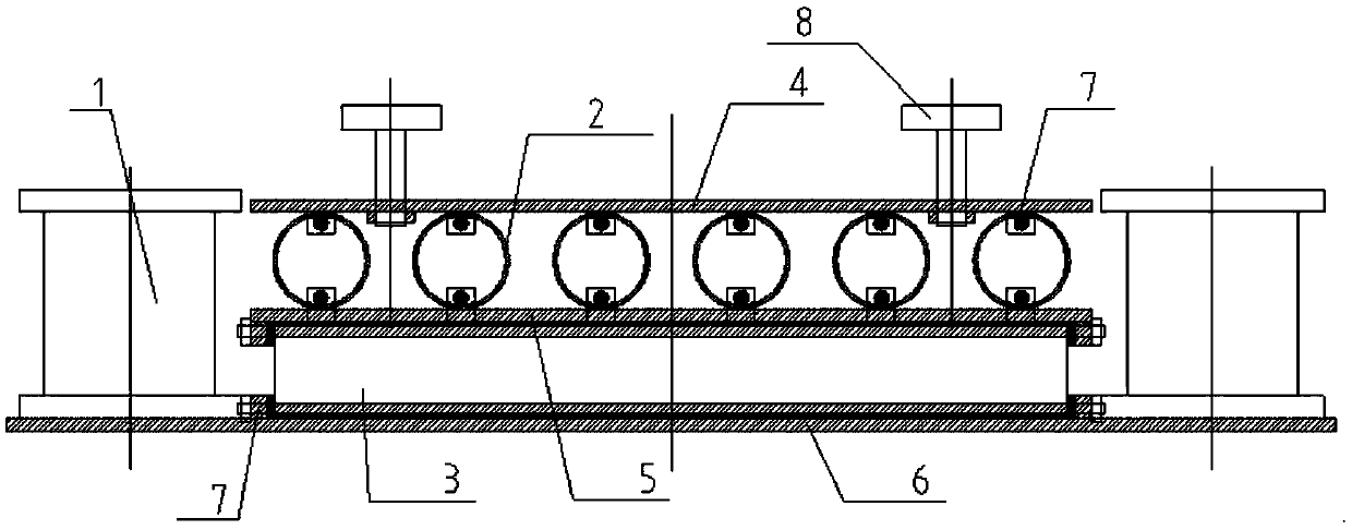
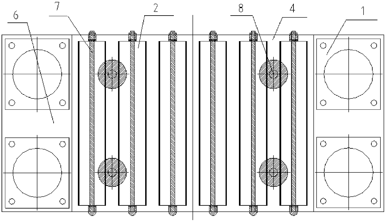
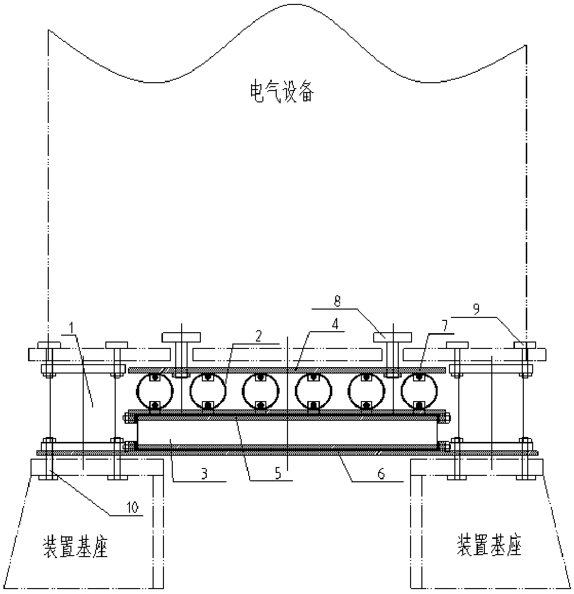
[0021] as attached figure 1 and 2 As shown, the present invention provides a vibration isolation and anti-shock device for electrical equipment,

[0022] GF1100A type composite damping vibration isolator 1 is connected to the lower mounting panel 6 (made of titanium alloy TC4 plate, thickness 16mm, size 1000mm*500mm) through bolts and nuts; the lower cylindrical shell 3 (made of TiNi alloy, wall thickness 1.0mm, diameter 80mm) , length 650mm) through the fixed connecting rod 7 (composed of vulcanized rubber vulcanized 1mm outside the stainless steel rod with a diameter of 10mm) and the lower installation panel 6 and the middle partition 5 (using titanium alloy TC4 plate, thickness 16mm, size 690mm*500mm ) is fixed; the upper cylindrical shell 2 (made of TiNi alloy, wall thickness 1.0mm, diameter 80mm, length 465mm) is connected with the upper mounting pa...


PUM


Abstract

The invention discloses an electrical equipment vibration isolation anti-impact device. The electrical equipment vibration isolation anti-impact device comprises composite damping vibration isolators,anti-impact cylindrical shell layers, an upper mounting panel, a lower mounting panel, an intermediate partition board and limiting screw rods. Each anti-impact cylindrical shell layer is composed oftwo or more layers of single cylindrical shells. Each cylindrical shell is made of a shape memory alloy material. The upper and lower anti-impact cylindrical shell layers are fixedly connected with the upper mounting panel and the lower mounting panel correspondingly. The adjacent anti-impact cylindrical shell layers are connected through the intermediate partition board. One ends of the composite damping vibration isolators are connected with the lower mounting panel, and the other ends of the composite damping vibration isolators are connected with electrical equipment. The lower mounting panel is connected with an external base. The limiting screw rods are fixedly connected with the upper mounting panel. The upper ends of the limiting screw rod go deep into an external electrical equipment base and are spaced from the electrical equipment base by a certain gap. The electrical equipment vibration isolation anti-impact device can improve the vibration isolation anti-impact capabilityof the electrical equipment to meet the design requirements for modularization and openness of the boat electrical equipment.

Description

technical field [0001] The invention belongs to the technical field of vibration isolation and anti-shock of ship equipment, in particular to a vibration isolation and anti-shock device for electrical equipment on a ship. Background technique [0002] For ship equipment, with the development of underwater weapons such as missiles, laser bombs, and depth charges, the explosive equivalent and impact duration have increased significantly, and precise computer guidance has greatly improved the hit rate of various underwater weapons. The continuous improvement of automation and informatization has led to the use of a large number of sophisticated electrical equipment for complex ship propulsion, navigation, command, control, and weapon systems, which are spread all over the ship, and the impact of underwater explosions on modern ship equipment, especially shipboard electrical appliances. The threat of equipment is more serious. In most cases, the ship hull itself may not be serio...

Claims


Application Information

Patent Timeline
Patent Type & Authority Applications(China)
IPC IPC(8): F16F15/06
CPCF16F15/06
Inventor 谭海涛李强张胜业郭寒贝
Owner NO 719 RES INST CHINA SHIPBUILDING IND
Why Eureka
Try Eureka