DC leakage current detecting device

A detection device and leakage current technology, applied in the direction of measuring device, only measuring current, measuring current/voltage, etc., can solve problems such as affecting the power supply of DC system, and achieve the effect of high cost performance, practical search, accurate detection and protection

Inactive Publication Date: 2019-03-26
BEIJING SMARTCHIP MICROELECTRONICS TECH COMPANY +1
View PDF7 Cites 9 Cited by
  • Summary
  • Abstract
  • Description
  • Claims
  • Application Information

AI Technical Summary

Problems solved by technology

[0007] The purpose of the present invention is to provide a detection device for DC leakage current, so as to overcome the disadvantage that the existing circuit detection method will affect the power supply of the DC system

Method used


Image

  • DC leakage current detecting device
  • DC leakage current detecting device
  • DC leakage current detecting device

Examples


Embodiment 1

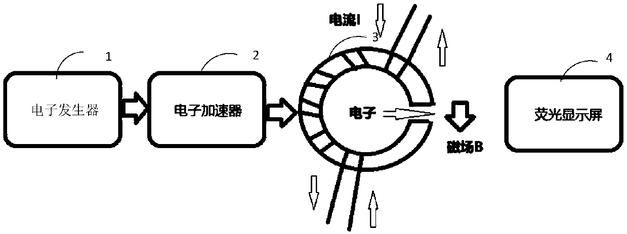
[0027] figure 1 A detection device for a DC leakage current provided in an embodiment of the present invention, the detection device includes: an electron emitter 1, an electron accelerator 2, an electromagnetic deflection coil 3, and a fluorescent display screen 4;

[0028] The electron emitter 1 is used to generate electron beams.

[0029] Specifically, the electron generator is responsible for generating charged particles. In the electron generator, after the filament is energized and heated, a large number of thermal electrons are generated on the surface. The filament must be made of a material with a high melting point and a high resistivity, generally made of tungsten wire. After passing a strong current, the filament is heated to more than 1,000 degrees. The cathode must be made of materials with low work function. The outer electrons of the atoms on the surface of the cathode, after being excited by a certain amount of heat or electric energy, will break away from th...

Embodiment 2

[0038] In this embodiment, on the basis of the first embodiment, the electromagnetic deflection coil is further limited for two kinds of circuits to be tested.

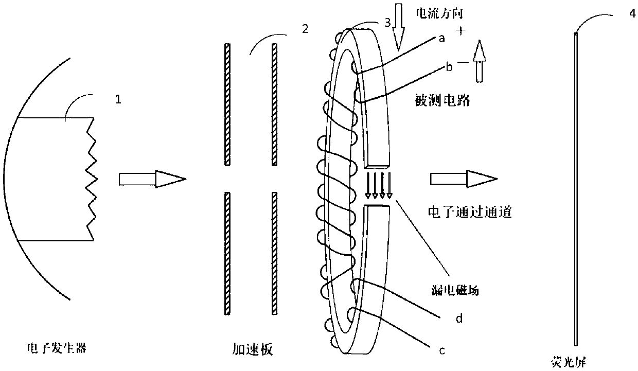
[0039] In one possible implementation, figure 2 For the detection device when the line to be tested provided by the embodiment of the present invention is the main circuit of the power supply, please refer to figure 2 , when the circuit to be tested is the main circuit of the power supply, the insulated wire is a double-branched wire, and the winding method and the number of turns of the double-branched wires are the same.

[0040] Specifically, the double-branch wire has a positive input terminal a, a positive output terminal c, a negative input terminal d, and a negative output terminal b. The positive input terminal a of the double-branch wire is connected to the positive pole of the power supply, and the negative output terminal b is connected to the negative pole of the power supply, and the positive pole output...

Embodiment 3

[0047] In this embodiment, on the basis of the above-mentioned embodiments, the arrangement direction of the electromagnetic deflection coil is further limited.

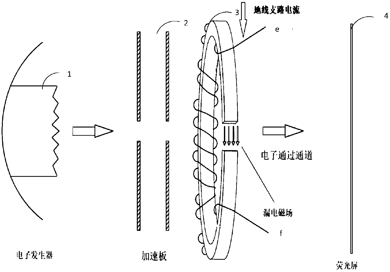
[0048] In one possible implementation, see figure 2 , image 3 , the magnetic core of the electromagnetic deflection coil is arranged perpendicular to the horizontal direction, and the magnetic field direction of the air gap is the vertical direction.

[0049] When there is no leakage current in the circuit to be tested, the electron beam forms dots or vertical lines on the fluorescent display screen.

[0050] Specifically, when no horizontal magnetic field is applied, electron beams form spots on the phosphor display screen. For the convenience of observation, a horizontal magnetic field can be applied to the air gap of the electromagnetic deflection coil. At this time, when there is no leakage current, the electron beams form vertical lines on the fluorescent display screen.

[0051] When there is a leakage cur...


PUM


Abstract

The invention discloses a DC (direct current) leakage current detecting device which comprises an electron emitter for generating an electron beam, an electron accelerator for accelerating electrons in the electron beam generated by the electron emitter to obtain electron energy, and an electromagnetic deflection coil comprising a magnetic core and an insulated wire wound on the magnetic core, wherein the magnetic core has an air gap, the insulated wire has an input end and an output end, the electromagnetic deflection coil is serially connected in a circuit to be detected according to the input end and the output end, and the electrons generated by the electron accelerator pass through the air gap of the electromagnetic deflection coil to strike a fluorescent display screen. According tothe DC leakage current detecting device provided in the embodiment, the magnitude of leakage current can be visually judged according to the position of an image on the fluorescent display screen, thepower supply quality of a line is not affected, and the detection is also convenient when the number of branches of a DC system is large.

Description

technical field [0001] The invention relates to a detection device, in particular to a detection device for DC leakage current. Background technique [0002] With the application of power system more and more widely, the security of power system becomes particularly important. [0003] The DC power supply equipment in the power system, as the security power supply and control signal power supply of the main electrical equipment, is a very large multi-branch power supply network. The reliable operation of the DC power system is the technical basis for ensuring the reliable operation of power. In the DC system, when the insulation level between the positive or negative pole of the DC system and the earth is lower than a certain value, it is called DC system grounding. The DC system has a wide distribution range and many exposed parts. When it is corroded by dust and moisture, the insulation of some weak insulation components will be reduced or the insulation will be damaged, ...

Claims


Application Information

Patent Timeline
Patent Type & Authority Applications(China)
IPC IPC(8): G01R19/00G01R31/02
CPCG01R19/0092G01R31/50
Inventor 王建李涛吴有超姚国旺刘瑞亓学庆
Owner BEIJING SMARTCHIP MICROELECTRONICS TECH COMPANY
Why Eureka
Try Eureka