Optical mirror magnetic suspension supporting device

A technology for optical mirrors and support devices, which is applied in the processing and support of large optical mirrors, support devices for optical mirrors, and magnetic levitation support devices for optical mirrors. The effect of service life, simple and reliable operation, and clean working environment

Inactive Publication Date: 2019-03-29
SHANDONG ZHONGHENG OPTOELECTRONIC TECH CO LTD
View PDF1 Cites 2 Cited by
  • Summary
  • Abstract
  • Description
  • Claims
  • Application Information

AI Technical Summary

Problems solved by technology

However, in the processing of large aperture and optical mirror, the difficulty of supporting the primary mirror also increases
At present, cylinder support and hydraulic support are mostly used as the main support methods in the support process of the optical primary mirror. There is a problem of cylinder oil leakage in the support process of the hydraulic cylinder support system, which will affect the use in the dust-free and pollution-free laboratory environment. It has an irreversible impact on the processing of large optical mirrors; the cylinder support method has poor stability and high repair rate, resulting in increased costs and reduced processing efficiency; and the above two support methods are inevitable in the vertical direction when adjusting the mirror surface. The energy loss caused by friction will affect the adjustment accuracy of the support force, thereby affecting the mirror processing accuracy

Method used


Image

  • Optical mirror magnetic suspension supporting device
  • Optical mirror magnetic suspension supporting device

Examples


Embodiment Construction

[0017] The present invention will be described in detail below in conjunction with the accompanying drawings and specific embodiments.

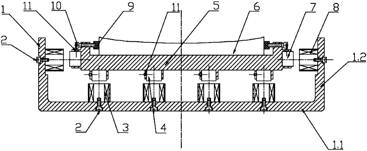
[0018] like figure 1 and figure 2 As shown, an optical mirror magnetic levitation support device includes an axial electromagnetic guide device, a radial electromagnetic guide device and an optical mirror surface fixing device;

[0019] Wherein the axial electromagnetic guiding device comprises an electromagnet mounting frame 1, some electromagnets-3 and some permanent magnets-4, the electromagnet mounting frame 1 comprises a circular base plate 1.1 and a vertical mounting plate 1.2 around the circular base plate edge, the electromagnet -3 is evenly installed on the bottom plate 1.1 of the optical mirror fixing device 5 through screws 2, and the permanent magnet-4 is evenly installed on the bottom of the optical mirror fixing device 5 through set screws 11, and the arranged permanent magnet-4 and electromagnet-1 Uniform one-to-one correspo...


PUM


Abstract

The invention discloses an optical mirror magnetic suspension supporting device. The optical mirror magnetic suspension supporting device comprises an axial electromagnetic guiding device, a radial electromagnetic guiding device and an optical mirror fixing device. In the axial electromagnetic guiding device, electromagnets I are uniformly mounted on a bottom plate at the lower end of the opticalmirror fixing device, and permanent magnets I are uniformly mounted at the bottom of the optical mirror fixing device. In the radial electromagnetic guiding device, electromagnets II are uniformly mounted on the inner sides of vertical mounting plates on the edge of an electromagnet mounting frame through screws, and permanent magnets II are uniformly mounted on the outer wall of the optical mirror fixing device through set screws. The side face of an optical mirror to be processed is limited and fixed to the optical mirror fixing device through locking screws. The optical mirror magnetic suspension supporting device can implement height supporting and posture adjustment on the mirror in the optical primary mirror processing process. The supporting device is effectively protected against damage caused by processing impact or vibration through flexible supporting. Meanwhile, the problems of friction, leakage, stagnation and the like occurring through an original supporting method are solved. The optical mirror magnetic suspension supporting device is easy to maintain and convenient to operate.

Description

technical field [0001] The invention relates to a support device for an optical mirror, in particular to a magnetic levitation support device for an optical mirror, especially suitable for processing and supporting a large optical mirror, and belongs to the technical field of optical mirror processing equipment. Background technique [0002] With the rapid development of optical technology, curved optical parts as the core components are widely used in military reconnaissance, aerospace and many civilian fields, such as projectors and camera lenses, viewfinders, telescopes and other fields, and modern optical systems It is rapidly developing in the direction of large diameter, high precision, high resolution and high power, and the demand for large optical mirrors is increasing, so there is a higher standard for the processing accuracy of optical mirrors. However, in the processing of large aperture and optical mirror, the difficulty of supporting the primary mirror also inc...

Claims


Application Information

Patent Timeline
Patent Type & Authority Applications(China)
IPC IPC(8): B24B13/005
CPCB24B13/005
Inventor 程刚金祖进顾伟张来宾崔振国郭锋
Owner SHANDONG ZHONGHENG OPTOELECTRONIC TECH CO LTD
Why Eureka
Try Eureka