
Prefabricated component assembling mold and use method

A technology of prefabricated components and combined molds, which is applied in the direction of molds, manufacturing tools, mold fixing devices, etc., can solve problems such as unfavorable demoulding, difficulty in not interfering with steel hooks, and short service life of molds.

Pending Publication Date: 2019-03-29
CHANGSHA BROAD HOMES IND GRP CO LED
View PDF7 Cites 8 Cited by
  • Summary
  • Abstract
  • Description
  • Claims
  • Application Information

AI Technical Summary

Problems solved by technology

This scheme is more suitable for the production of closed stirrup shear walls. However, due to the large number of slots, the rigidity of the mold is affected, and the deformation of the mold is more obvious in the later period. Manual plugging is required, the efficiency is low, and it is easy to find out the leakage of slurry
Secondly, if the component is an open stirrup, or if there are many shear parts on the side, the slotting method is not conducive to demoulding, and it is difficult to ensure that the notch and the steel bar hook do not interfere during the demoulding process

Method used


Image

  • Prefabricated component assembling mold and use method
  • Prefabricated component assembling mold and use method
  • Prefabricated component assembling mold and use method

Examples


Embodiment Construction

[0027] The present invention will be further described below in conjunction with the accompanying drawings and embodiments.

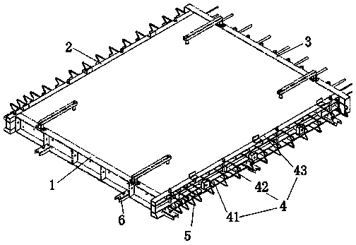
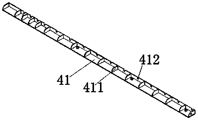
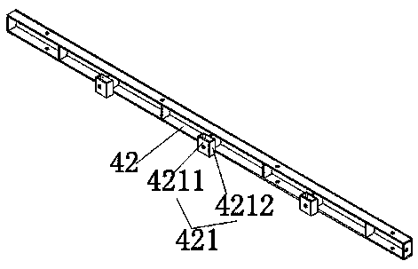
[0028] refer to Figure 1~5 : A kind of prefabricated component composite mould, comprises the lower side mold and three side molds that are used to encircle and form the prefabricated component pouring cavity, the side molds include the upper side mold, the middle side mold and the lower side mold, and the lower side mold is provided with the first A reinforcement hole is installed under the middle side formwork; a second reinforcement hole is provided on the upper side formwork and installed above the middle side formwork; a first demoulding device is installed on the side of the middle side formwork away from the prefabricated components, and the middle side formwork , the lower side mold and the upper side mold are connected.

[0029] In this embodiment, the three side molds are the left mold 2, the right mold 4 and the upper mold 3, the first stee...


PUM


Abstract

The invention discloses a prefabricated component assembling mold which comprises a lower side mold body and three side mold bodies for defining a prefabricated component pouring cavity. Each side mold body comprises an upper side mold main body, a middle side mold main body and a lower side mold main body, wherein the lower side mold main body is provided with first reinforcing steel bar holes and installed on the lower side of the middle side mold main body, the upper side mold main body is provided with second reinforcing steel bar holes and installed on the upper side of the middle side mold main body, the side, away from a prefabricated component, of the middle side mold main body is provided with a first demolding device, and the middle side mold main body, the lower side mold main body and the upper side mold main body are connected with one another. By means of the three-layer combined mold formed by the side mold main bodies on the upper side, the left side and the right side,the demolding process can be simple and efficient; the middle side mold main bodies are provided with no open grooves and are high in integrity and not prone to deformation; after the mold is installed, no clogging is needed, the operation steps are reduced, the mold assembling efficiency is improved, and the component forming quality is high.

Description

technical field [0001] The invention relates to the field of prefabricated components, in particular to a combined mold for prefabricated components and a use method. Background technique [0002] Steel bars protrude from three sides of the prefabricated component. For the steel bars protruding from the left and right sides, the current common practice is to use profile openings, and the steel bars pass through the notch of the mold, and then seal the notch and pour the component concrete. This scheme is more suitable for the production of closed stirrup shear walls. However, due to the large number of slots, the rigidity of the mold is affected, and the deformation of the mold is more obvious in the later period. Manual plugging is required, the efficiency is low, and it is easy to find out the leakage of slurry. Secondly, if the component is an open stirrup, or if there are many shear parts on the side, the slotting method is not conducive to demoulding, and it is difficu...

Claims


Application Information

Patent Timeline
Patent Type & Authority Applications(China)
IPC IPC(8): B28B7/10B28B7/00
CPCB28B7/0002B28B7/0014B28B7/0017B28B7/002B28B7/10
Inventor 张剑王雅明李融峰徐雷周涛
Owner CHANGSHA BROAD HOMES IND GRP CO LED
Learn More