Bicycle structure
A bicycle and body technology, applied in the field of bicycle structure, can solve the problems of difficult parking, long time consumption, and chaotic storage of self-propelled vehicles, so as to improve passability and loading convenience, improve convenience and quantity, and reduce bicycles The effect of width
- Summary
- Abstract
- Description
- Claims
- Application Information
AI Technical Summary
Problems solved by technology
Method used
Image
Examples
Embodiment 1
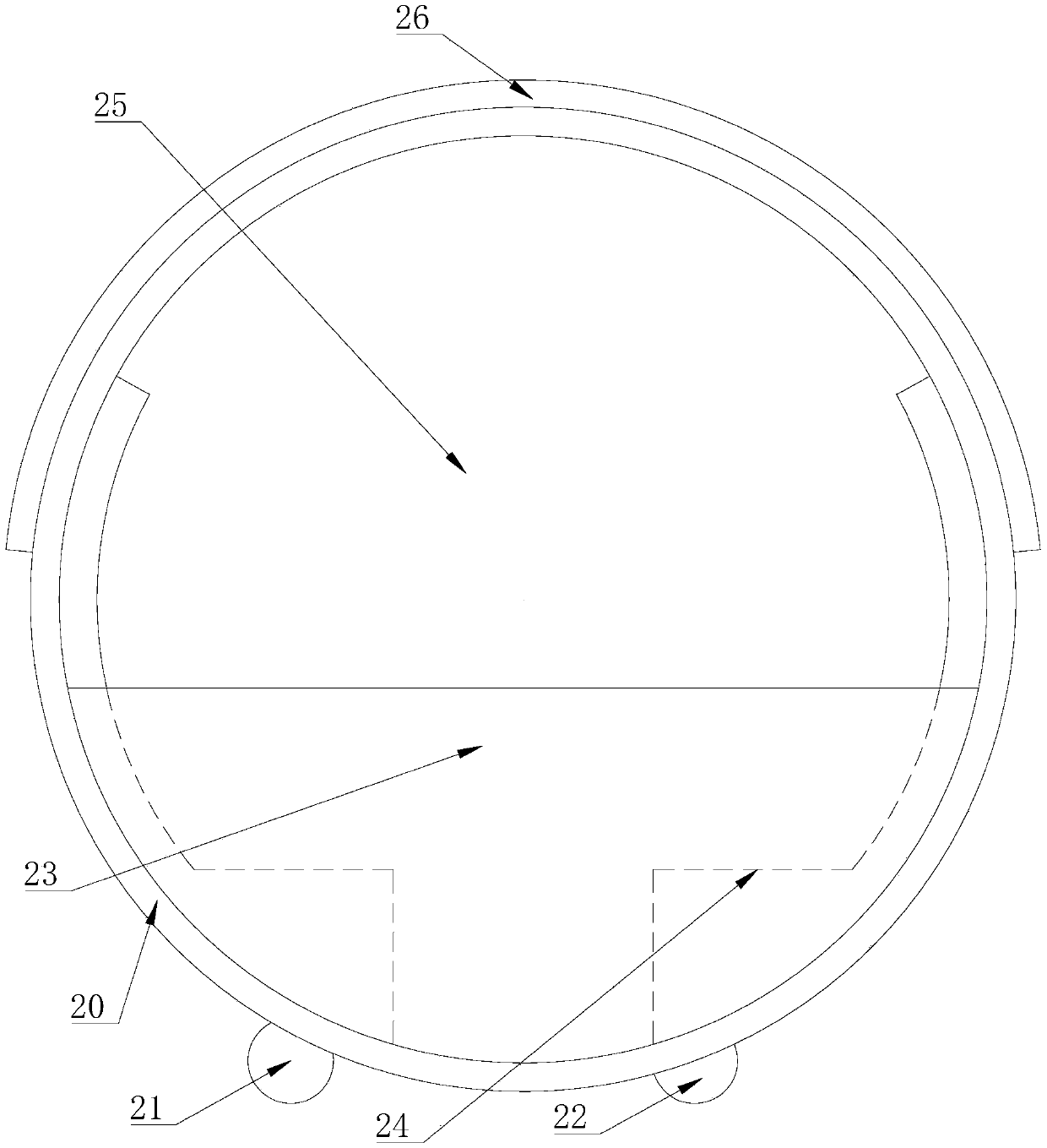
[0034] Such as Figure 2 to Figure 5 As shown, a bicycle structure is introduced in this embodiment, which includes a vertically extending circular vehicle body body 20 with a certain extension width. Seats 24 for passengers to sit on are installed. The bicycle structure introduced in this embodiment can be used as the second vehicle 2 in the following embodiments, so as to be carried on the first vehicle 1 for passengers to commute from a fixed station to a destination, and from an origin to a fixed station. .
[0035] By setting the bicycle in a vertical ring-shaped structure, so that the entire outer contour of the bicycle is composed of a circular arc surface, so as to reduce the impact force caused by the collision of the bicycle, thereby improving the passability and loading convenience of the bicycle; At the same time, seats are arranged inside the bicycle to minimize the width of the bicycle, thereby reducing the area of parking space occupied by the vehicle, and i...
Embodiment 2
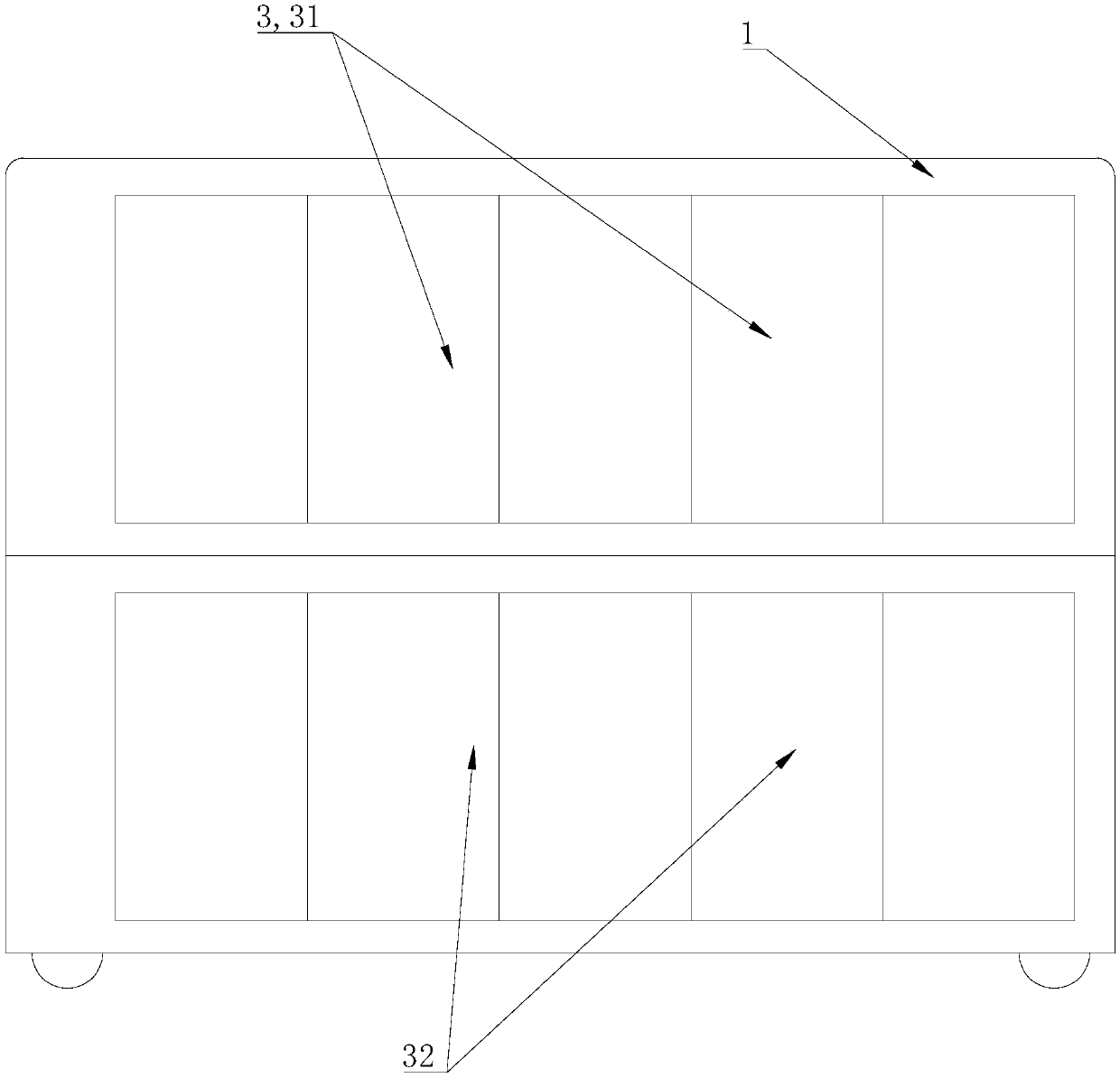
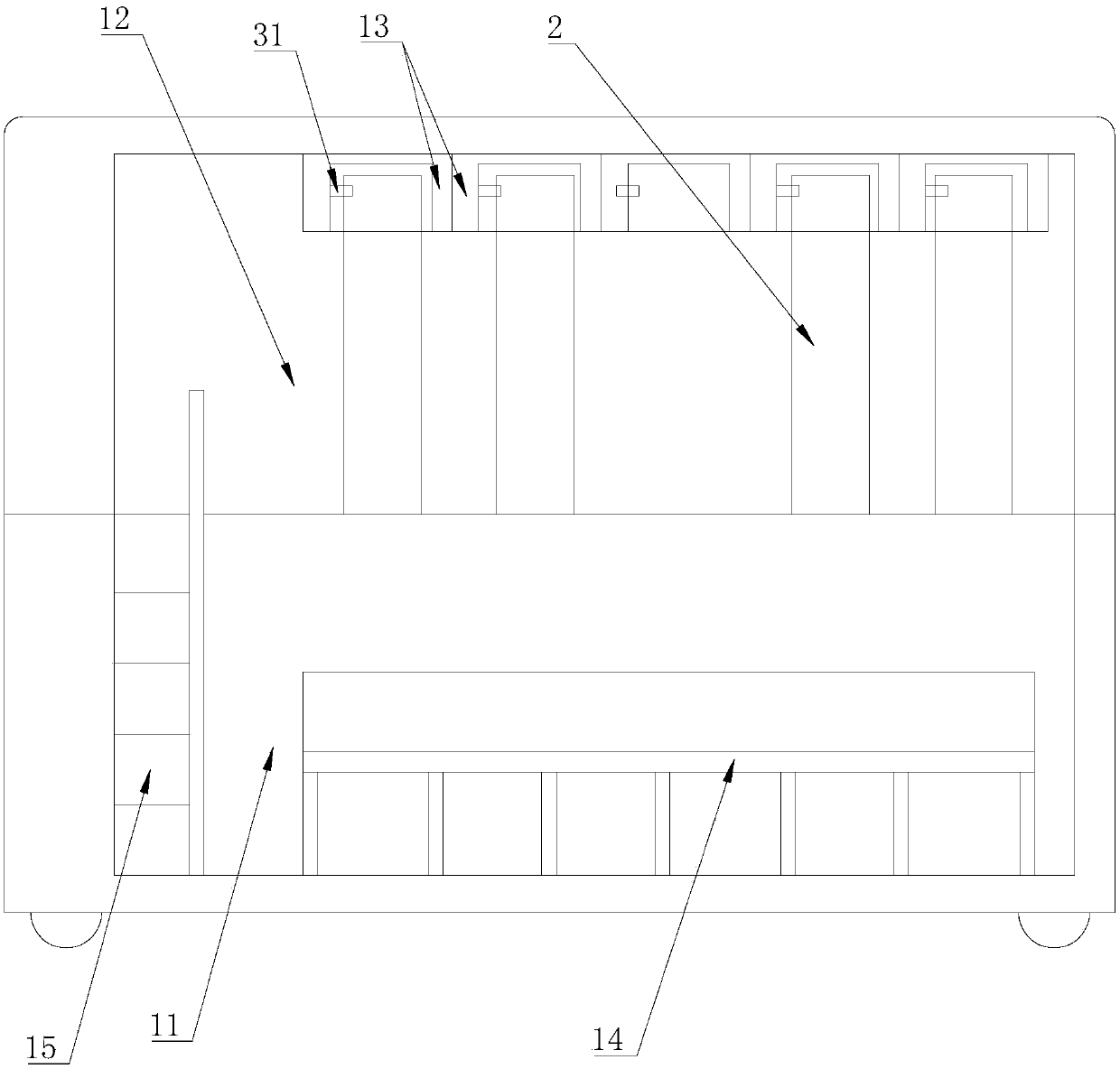
[0047] Such as figure 1 , figure 2 , Figure 5 As shown, a vehicle structure is provided in this embodiment, which includes: a first vehicle 1, which travels along a fixed route and stops at a fixed site; a second vehicle 2, which is used by passengers alone and travels freely; the first vehicle 1 A seating area 11 for passengers and a parking area 12 for the second vehicle 2 are provided in the compartment, so that multiple second vehicles 2 can be mounted on the parking area 12 of the first vehicle 1 up and down.
[0048] By carrying a second vehicle that can be used as a self-passenger vehicle on the first vehicle of the public transport, passengers can use the second vehicle to go between the fixed station and the destination, or between the origin, greatly improving the passenger's safety. Commuting efficiency; at the same time, since the second vehicle can be carried on the first vehicle, the second vehicle used for commuting to and from the passenger can move togethe...
Embodiment 3
[0058] Such as Figure 5 As shown, this embodiment introduces a platform 4 for the application of the vehicle structure described in the second embodiment above, which includes: a first platform 41, and a first door body 31 corresponding to the seating area 11 of the first vehicle 1 The second platform 42 is arranged opposite to the second door 32 corresponding to the parking area 12 of the first vehicle 1 for the second vehicle 2 to get on and off.
[0059] By setting different platform areas, passengers and the second vehicle can respectively get on and off at corresponding independent platforms, effectively avoiding contact between passengers and the second vehicle, and improving the efficiency of getting on and off.
[0060] In the present embodiment, the platform 4 includes a first platform 41 and a second platform 42 arranged up and down, and the platform surface of the first platform 41 is flush with the bottom surface of the lower seating area 11 of the double-deck fir...
PUM
| Property | Measurement | Unit |
|---|---|---|
| Width | aaaaa | aaaaa |
Abstract
Description
Claims
Application Information
 - R&D
- Intellectual Property
- Life Sciences
- Materials
- Tech Scout
- Unparalleled Data Quality
- Higher Quality Content
- 60% Fewer Hallucinations
Browse by: Latest US Patents, China's latest patents, Technical Efficacy Thesaurus, Application Domain, Technology Topic, Popular Technical Reports.
© 2025 PatSnap. All rights reserved.Legal|Privacy policy|Modern Slavery Act Transparency Statement|Sitemap|About US| Contact US: help@patsnap.com


