Carbon fiber composite aircraft window frame and manufacturing method thereof

A manufacturing method and carbon fiber technology are applied in the field of carbon fiber composite aircraft window frames and their manufacturing, and can solve problems such as the inability of metal materials to meet requirements.

Inactive Publication Date: 2019-03-29
HENGSHEN
View PDF9 Cites 2 Cited by
  • Summary
  • Abstract
  • Description
  • Claims
  • Application Information

AI Technical Summary

Problems solved by technology

The traditional aircraft window frame material is made of aluminum alloy, each weighing about 2.1KG. Due to the development of lightweight aerospace, traditional metal materials cannot meet the requirements

Method used


Image

  • Carbon fiber composite aircraft window frame and manufacturing method thereof
  • Carbon fiber composite aircraft window frame and manufacturing method thereof
  • Carbon fiber composite aircraft window frame and manufacturing method thereof

Examples


Embodiment Construction

[0018] Embodiments of the present invention will be described in detail below in conjunction with the accompanying drawings.

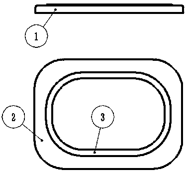
[0019] like figure 1 As shown, a carbon fiber seamed aircraft window frame includes a flange 1, a web 2 and a lip 3, and the web 2 is connected to the fuselage skin by fasteners. The window frame is a laminated structure, adopts an integrated design, and is formed as a whole. After laying the sub-prefabricated body, it is RTM formed, and the transparent part is clamped in the variable thickness area.

[0020] The manufacturing method of the carbon fiber jointed aircraft window frame specifically comprises the following steps:

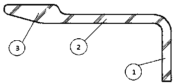
[0021] Step 1: Through the joint laying process, four sub-prefabricated bodies are manufactured; as image 3 shown.

[0022] Step 2: Lay the four sub-prefabricated bodies in a certain order into the inner cavity of the mold, and then put them into the oven to prepare the prefabricated body of the entire aircraft window frame....


PUM


Abstract

A carbon fiber composite aircraft window frame comprises a flange (1), a web (2) and a lip (3). The web is connected with fuselage skin through a fastener. Compared with an aluminum alloy aircraft window frame, the weight is reduced by about 40%; the anisotropy characteristic of a composite is brought into full play, and the continuity characteristic of fiber along a main force transmitting routeis kept to a great extent.

Description

technical field [0001] The invention relates to a carbon fiber jointed aircraft window frame, in particular to a carbon fiber composite material aircraft window frame and a manufacturing method thereof. Background technique [0002] The aircraft window frame is a load-bearing component on the fuselage, a large opening reinforcement structure, and its main function is to reinforce the partial openings on the fuselage. Traditional aircraft window frames are made of aluminum alloy, each weighing about 2.1KG. Due to the development of lightweight aerospace, traditional metal materials cannot meet the requirements. [0003] Compared with traditional metal materials, carbon fiber composite materials have the advantages of strong designability, high specific strength, high specific modulus, light weight, corrosion resistance, fatigue resistance, shock absorption and noise reduction, etc., and have been widely used in automobiles, rail transit, aerospace and many other fields. The...

Claims


Application Information

Patent Timeline
Patent Type & Authority Applications(China)
IPC IPC(8): B64C1/14B64F5/10
CPCB64C1/14B64F5/10
Inventor 尚云东石双仇亚萍马兴虎
Owner HENGSHEN
Why Eureka
Try Eureka