
A transmission mechanism of a foam back glue laminating machine

A technology of transmission mechanism and cotton adhesive, which is applied in the direction of adhesives, film/sheet adhesives, and thin material processing, etc. It can solve problems such as easy generation of air bubbles and wrinkles, and affect the quality of foam double-sided adhesives. It is not easy to achieve The effect of loosening and tight connection

Active Publication Date: 2020-06-12
重庆安洁电子有限公司
View PDF7 Cites 0 Cited by
  • Summary
  • Abstract
  • Description
  • Claims
  • Application Information

AI Technical Summary

Problems solved by technology

But there are following problems in above-mentioned scheme: 1, when sticking between foam cotton and double-sided adhesive tape, very easily produce air bubble and wrinkle between the two, influence the quality of foam cotton double-sided adhesive; 2, in the material receiving machine of this device , it is difficult to remove the double-sided foam tape after receiving the material

Method used


Image

  • A transmission mechanism of a foam back glue laminating machine
  • A transmission mechanism of a foam back glue laminating machine
  • A transmission mechanism of a foam back glue laminating machine

Examples


Embodiment Construction

[0020] The following is further described in detail through specific implementation methods:

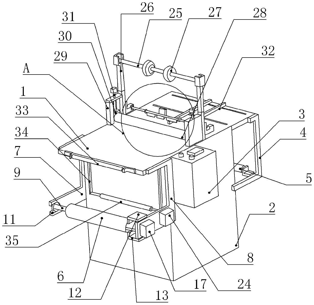
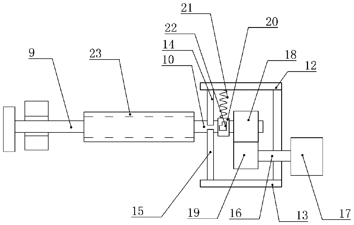
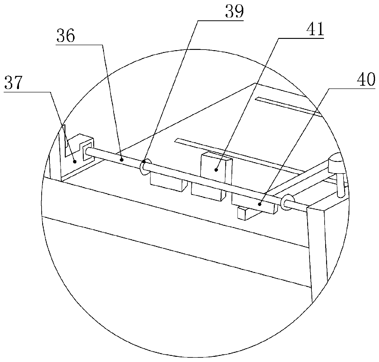
[0021] The reference signs in the accompanying drawings of the description include: platform 1, base 2, control box 3, feeding frame 4, feeding roller 5, receiving roller 6, first frame 7, second frame 8, first pole 9, The second pole 10, the U-shaped groove 11, the first horizontal plate 12, the second horizontal plate 13, the first fixed rod 14, the second fixed rod 15, the rotating shaft 16, the first motor 17, the first gear 18, the second Gear 19, arc plate 20, first spring 21, handle 22, air bag 23, air pump 24, horizontal rod 25, vertical rod 26, fixed wheel 27, pressure roller 28, U-shaped frame 29, fixed block 30, screw rod 31 , guide rod 32, first conveying roller 33, U-shaped guide frame 34, second conveying roller 35, support rod 36, L-shaped frame 37, second spring 38, impression roller 39, pressing plate 40, push rod 41.

[0022] Example figure 1 and figure 2 Shown:...


PUM


Abstract

The invention relates to the technical field of foam and back gum, and discloses a drive mechanism of a foam and back gum laminating machine. The foam and back gum laminating machine comprises a platform, a feeding mechanism and a material rolling mechanism; the material rolling mechanism comprises a material rolling frame and a material rolling roller, the material rolling frame comprises a firstframe and a second frame, two sides of the material rolling roller are fixedly connected with a first supporting rod and a second supporting rod respectively, one side of the second frame is fixedlyconnected with a first horizontal plate and a second horizontal plate, the side, far away from the first frame, of the second frame is rotationally connected with a rotating shaft, one end of the rotating shaft is fixedly connected with a first motor, the other end of the rotating shaft is fixedly connected with a first gear, the end part of the second supporting rod is fixedly connected with a second gear, an air bag is fixedly connected to the outer side of the material rolling roller, and an air pump is arranged on the second frame. According to the machine, bubbles and wrinkles between thefoam and double-faced adhesive tape are eliminated, and the defective rate of the ultrathin foam double-faced adhesive tape is reduced; and an adjustable material rolling machine is arranged, so thatthe ultrathin foam double-faced adhesive tape can be conveniently taken.

Description

technical field [0001] The invention relates to the technical field of foam adhesive, in particular to a transmission mechanism of a foam adhesive bonding machine. Background technique [0002] Ultra-thin foam adhesive, also known as ultra-thin foam double-sided adhesive tape, includes the base material layer of the double-sided adhesive tape, the adhesive layer of the double-sided adhesive tape and foam, and the adhesive layer of the double-sided adhesive tape needs to be pasted On the foam, when the user uses it, tear off the base material layer of the double-sided adhesive strip, and then paste the foam on the article through the adhesive layer of the double-sided adhesive strip. This ultra-thin foam double-sided adhesive is mainly used for in the laptop. At present, when making ultra-thin foam double-sided adhesive tape, the double-sided adhesive tape and the foam are pasted manually, which may easily lead to inconsistent bonding or poor bonding effect. [0003] For th...

Claims


Application Information

Patent Timeline
Patent Type & Authority Patents(China)
IPC IPC(8): B65H20/02B65H18/10B65H18/02B65H18/26B65H19/30B65H37/04B65H75/24C09J7/26
CPCB65H18/028B65H18/10B65H18/26B65H19/30B65H20/02B65H37/04B65H75/243B65H2301/417B65H2701/11332C09J7/26
Inventor 淡克平
Owner 重庆安洁电子有限公司
Learn More