Manufacturing method of prefabricated column, assembly method of column and beam

A prefabricated column and tooling positioning technology, which is applied to columns, piers, pillars, etc., can solve the problems of difficult on-site operation of column and beam installation, high maintenance cost in the whole life cycle, inconvenient production and manufacture of prefabricated columns, etc., and achieves easy control of installation accuracy. , Improve construction efficiency and construction quality, without the effect of operating space restrictions

Active Publication Date: 2020-03-31
CHINA CONSTR SCI & TECH CO LTD
View PDF5 Cites 0 Cited by
  • Summary
  • Abstract
  • Description
  • Claims
  • Application Information

AI Technical Summary

Problems solved by technology

[0006] The technical problem to be solved by the present invention is to provide a steel structure node, a prefabricated column and its manufacturing method, and a column-beam assembly method, aiming at solving the inconvenience of prefabricated column production in the beam-column connection form in the prior art, Easy to store and transport, difficult to operate on-site for column and beam installation, uncontrollable installation accuracy and high maintenance cost in the whole life cycle

Method used


Image

  • Manufacturing method of prefabricated column, assembly method of column and beam
  • Manufacturing method of prefabricated column, assembly method of column and beam
  • Manufacturing method of prefabricated column, assembly method of column and beam

Examples


Embodiment 1

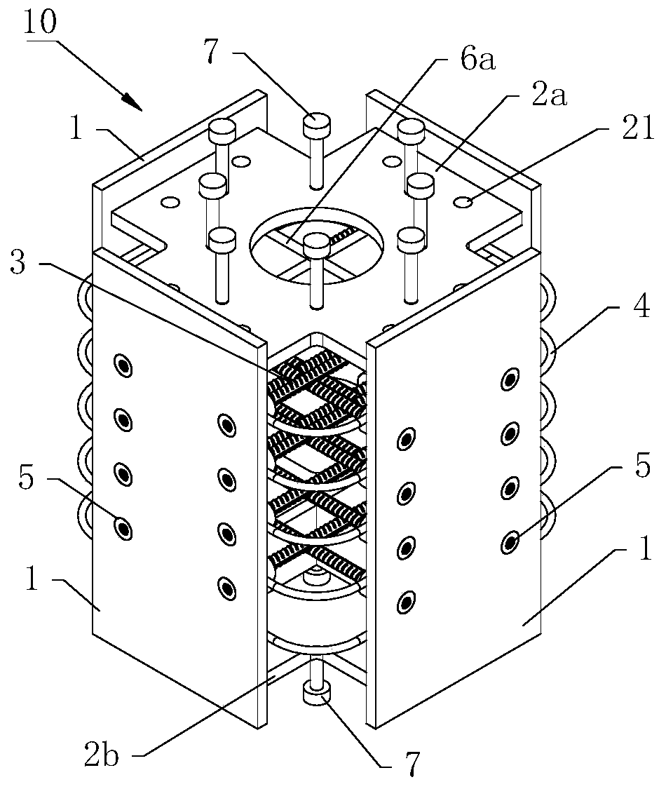
[0080] See figure 1 , shows a steel structure node 10 provided in this embodiment, including a side plate 1 on the side, a top plate 2a on the top, several pairs of tie rods 3, several stirrups 4, first high-strength bolt sleeves 5, middle The cross plate 6a and the bottom plate 2b at the bottom.

[0081] In this embodiment, the side surfaces of the top plate 2a and the bottom plate 2b both extend out from the connecting portion, and both the top plate 2a and the bottom plate 2b are in the shape of a cross. Both the connecting portion of the top plate 2a and the connecting portion of the bottom plate 2b are provided with a plurality of perforations 21 along their respective thickness directions, and the reserved holes 21 are used for the steel bars of the reinforcement cage to pass through.

[0082] The connecting portion of the top plate 2a is fixedly connected to the top inner surface of the side plate 1, and the connecting portion of the bottom plate 2b is fixedly connecte...

Embodiment 2

[0143] See Figure 18 , the present embodiment provides another steel structure node 10, including a side plate 1 on the side, a top plate 2a on the top, several pairs of tie rods 3, several stirrups 4 and a bottom plate 2b.

[0144] Except for the content mentioned below, the steel structure node 10 of this embodiment is the same as that of Embodiment 1:

[0145] In this embodiment, a second high-strength bolt sleeve 8 is embedded in the perforations on the top plate 2a and the bottom plate 2b, and the second high-strength bolt sleeve 8 protrudes from the plane of the top plate 2a. The second high-strength bolt sleeve 8 is installed on the two ends of the vertical pull bolt 9, and the second high-strength bolt sleeve 8 on the top plate 2a and the second high-strength bolt sleeve 8 on the bottom plate 2b pass through the vertically arranged pull bolt. Bolt 9 connection.

[0146] The connecting portion of the top plate 2 a is fixedly connected to the top surface of the side p...


PUM


Abstract

The invention belongs to the technical field of building construction, and provides a steel structure joint, a prefabricated column, a manufacturing method thereof and an assembling method of a columnbeam. The steel structure joint is reliable in stress and convenient to produce and manufacture; the prefabricated column with the steel structure joint is easy to transport and store, the installingprocess of a steel beam and the prefabricated column on site is easy and convenient, operation is convenient, no formwork erection is needed on site, supporting is easy, no operation space limit is caused, dry type construction is performed, the installing precision is easy to control, the later corrosion resistance and fireproof treating area is small, the full-life-cycle maintenance cost is low, the advantages of a fabricated building is sufficiently reflected, the construction efficiency and the construction quality are improved, and waste and building waste are reduced.

Description

technical field [0001] The invention belongs to the technical field of building construction, and in particular relates to a steel structure node, a prefabricated column and a manufacturing method thereof, and an assembly method of a column and beam. Background technique [0002] At present, beam-column joints mainly have the following connection forms: [0003] One of them is the beam-column joint in the prefabricated prefabricated concrete structure. Generally, post-cast sections are set in the joint area to realize the connection between the prefabricated reinforced concrete column and the concrete beam. Although this kind of joint is reliable in force, there are many problems in the core area of ​​the joint, such as many steel bars, easy to conflict with each other, narrow operating space, difficult lifting of concrete beams, formwork required for on-site installation, and low installation efficiency. [0004] The other is the joint between the prefabricated reinforced ...

Claims


Application Information

Patent Timeline
Patent Type & Authority Patents(China)
IPC IPC(8): E04C3/34E04B1/58E04G21/14B28B23/02B28B1/08
CPCB28B1/08B28B23/02E04B1/58E04C3/34E04G21/14
Inventor 孙占琦邱勇王洪欣芦静夫崔燕辉王庆华李晓丽
Owner CHINA CONSTR SCI & TECH CO LTD
Why Eureka
Try Eureka