Axial flow fan blade, ventilating device and air conditioner

An axial flow fan blade and blade technology, which is applied in the field of impeller machinery, can solve the problems of the air volume of the axial flow fan blade falling, rising, and reducing the working capacity of the blades 4, and achieves the effect of improving the working capacity and reducing the noise of the fan blade.

Pending Publication Date: 2019-03-29
GREE ELECTRIC APPLIANCES INC
View PDF0 Cites 2 Cited by
  • Summary
  • Abstract
  • Description
  • Claims
  • Application Information

AI Technical Summary

Problems solved by technology

Obviously, after adopting such a single-folded or bent structure with the pressure facing the suction surface, the working ability of the blade 4 near the blade tip will be reduced, that is, the pressure on the pressure surface near the blade tip will decrease, and the pressure on the suction surface will increase, resulting in 4 The working ability here is reduced, and the air volume generated by the axial fan blades is reduced

Method used


Image

  • Axial flow fan blade, ventilating device and air conditioner
  • Axial flow fan blade, ventilating device and air conditioner
  • Axial flow fan blade, ventilating device and air conditioner

Examples


Embodiment 1

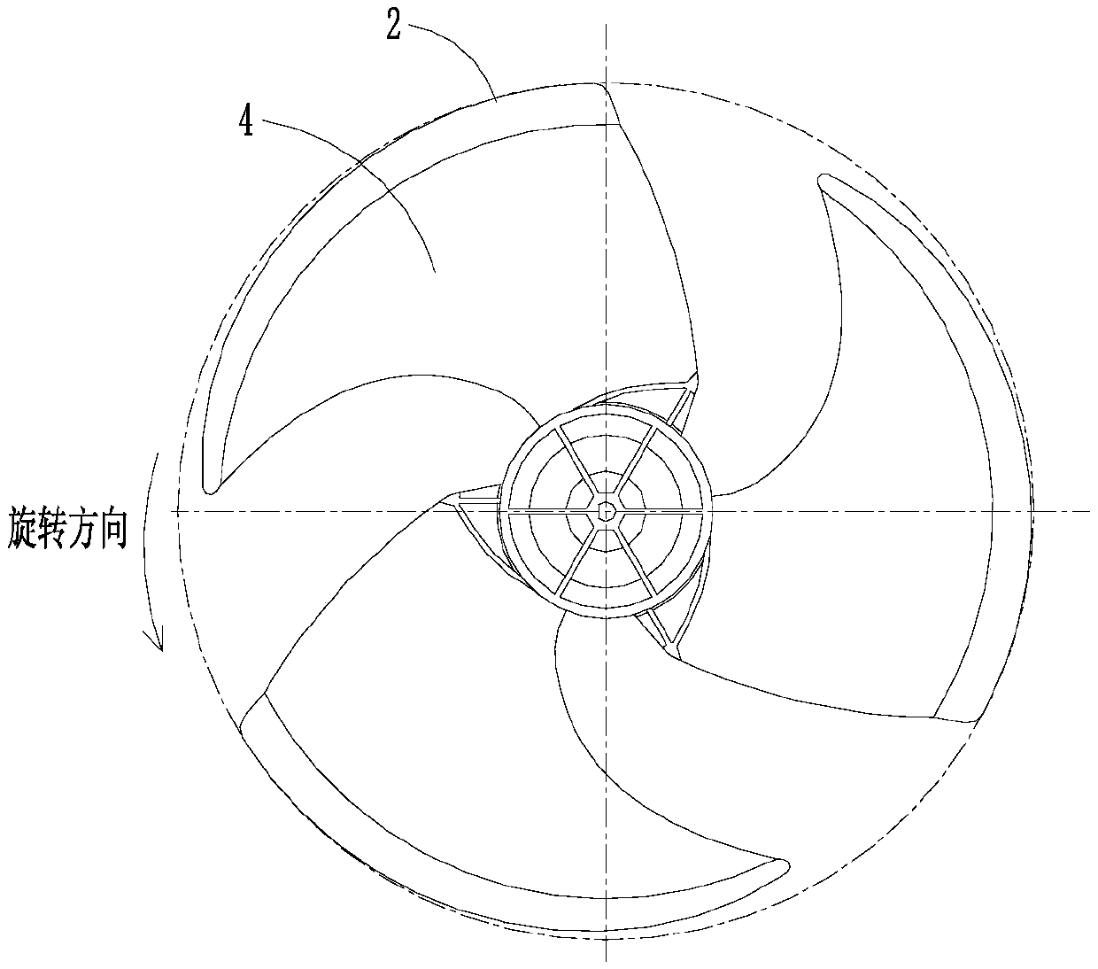
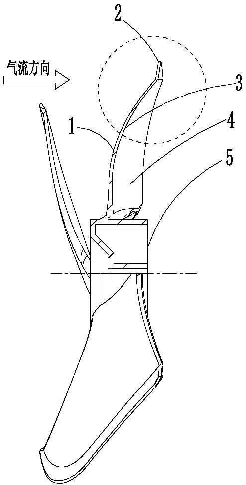
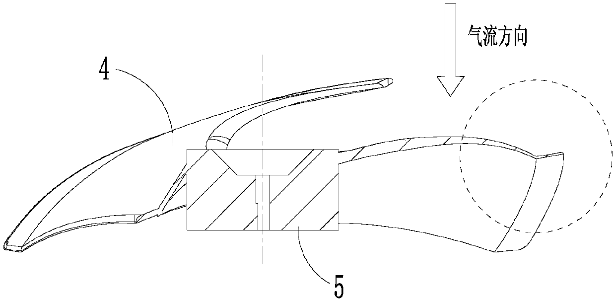
[0065] Picture 11 This is a schematic diagram of the front view structure of Embodiment 1 of this application. Picture 12 This is a schematic diagram of a side view structure of an embodiment of this application, Figure 13 This is a schematic diagram of the top view structure of Embodiment 1 of this application, Figure 14 This is a detailed structural schematic diagram of the bending of the blade top in Example 1 of this application.

[0066] As shown in the figure, the entire range of the tip 2 of the blade 4 is provided with bends to the pressure surface 3 and the suction surface 1, that is, the first side 21 and the second side 22, and the entire tip 2 is type( The upper end is the blade tip 2), or the structure with hemmed edges, is in a "Y" shape (the upper end of the Y is the blade tip 2). Among them, the first side 21 is bent to the suction surface 1 to one side to produce a structure with a bending radius of R1, thereby ensuring that the positive pressure area of ​​th...

Embodiment 2

[0070] Figure 15 This is a schematic diagram of the front view structure of Embodiment 2 of this application. Figure 16 This is a schematic diagram of the side view structure of the second embodiment of this application, Figure 17 This is a schematic diagram of the top view structure of Embodiment 2 of this application, Figure 18 This is a detailed structural diagram of the second embodiment of the bending structure of this application, and Figure 19 This is a schematic diagram of the structure of the folding or bending area of ​​the leaf top in the second embodiment of this application.

[0071] As shown in the figure, in the partial range of the tip 2 of the blade 4, there are bends to the pressure surface 3 and the suction surface 1 respectively, and the partial range of the tip is Figure 19 From b1 to the outermost dot of the leading edge of the blade 4, the starting position of the bend or edge along the airflow direction, the angle between the two points and the center o...

Embodiment 3

[0076] Picture 20 This is a detailed schematic diagram of the folding structure of the third embodiment of this application. As shown in the figure, the first edge 21 and the second edge 22 are respectively folded edges, wherein the angle between the first edge 21 and the blade 4 is a1, and the angle between the second edge 22 and the blade 4 is a3, the relationship between the two It is a1≤a3, or R1≤R3. The bending or hemming structure toward the pressure surface can even be approximated as a straight plate "y" (the upper end of y is the tip of the blade), that is, R3 is infinite or a3=180°.


PUM


Abstract

The invention relates to the technical field of impeller machinery, and provides an axial flow fan blade, a ventilating device and an air conditioner. The axial flow fan blade comprises a hub and a plurality of blades, the two sides of each blade are a pressure surface at an air outlet side and a suction surface at an air inlet side respectively, the radial outward edge part of each blade is a blade top, the blade top of each blade is provided with a first edge and a second edge, the first edge is bent and extends towards the suction surface, and the second edge is bent and extends towards thepressure surface. According to the axial flow fan blade disclosed by the invention, the power capacity of the blades can be improved, the control of the blade top leakage vortex is realized and the fan blade noise is reduced.

Description

Technical field [0001] This application relates to the technical field of impeller machinery, in particular to an axial flow fan, a ventilation device and an air conditioner. Background technique [0002] In order to realize the circulation of air, various blades are usually used in the ventilation device. The basic structure of the general blade includes a hub as a rotating shaft and a plurality of blades arranged radially on the outer periphery of the center. The leading edge of the blade flows in and blows out from the trailing edge of the blade after the blade is pressurized, thereby forming a pressure surface and a suction surface. [0003] During the operation of the existing axial flow blades, a low pressure area, or vortex, is often generated in the middle part of the tip of the suction surface. The vortex is mainly flowed from the high pressure area of ​​the pressure surface of the blade to the low pressure area of ​​the suction surface. As a result, this phenomenon is ca...

Claims


Application Information

Patent Timeline
Patent Type & Authority Applications(China)
IPC IPC(8): F04D29/38F04D29/66
CPCF04D29/388F04D29/666F04D29/667
Inventor 刘中杰曹锋和浩浩邹建煌
Owner GREE ELECTRIC APPLIANCES INC
Why Eureka
Try Eureka