Environment-friendly flue gas circulation layer-burning boiler and treatment method thereof
A treatment method and boiler technology, applied in the direction of combustion method, combustion equipment, fuel supply, etc., can solve problems such as difficulty in popularization, achieve the effect of reducing heat loss and improving fuel burnout rate
- Summary
- Abstract
- Description
- Claims
- Application Information
AI Technical Summary
Problems solved by technology
Method used
Image

Examples
Embodiment 1
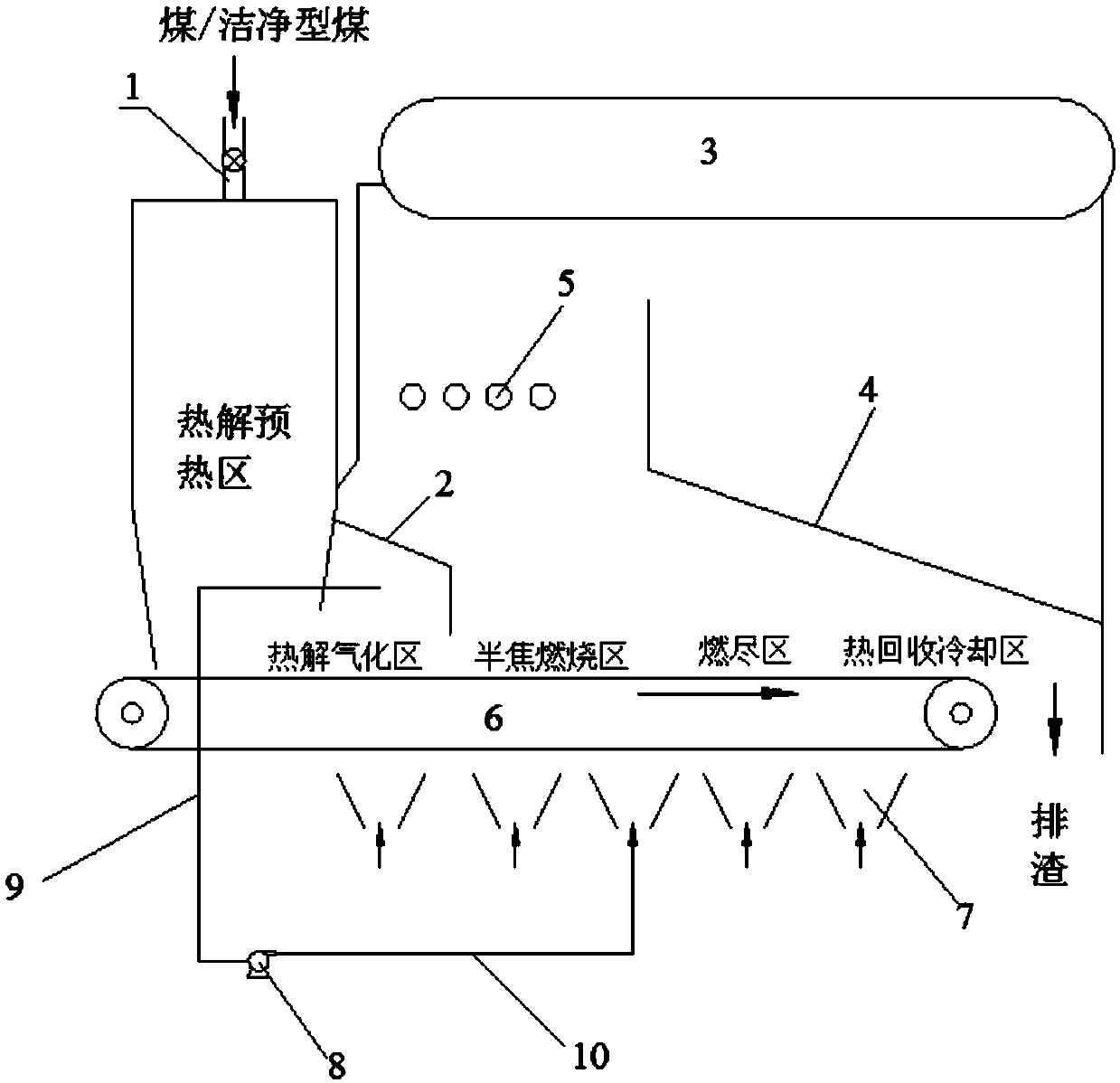
[0059] This embodiment part provides a kind of layer fired boiler, such as figure 1 As shown, the furnace body of the layer-fired boiler includes a first cavity and a second cavity connected at the bottom; the top and / or side of the first cavity is provided with a coal filling port 1, and the first cavity The inside is a pyrolysis preheating zone; the inside of the second cavity is provided with a folded line partition 2, and the folded line partition 2 is connected to the first part of the connection between the first cavity and the second cavity. The outer wall of the cavity is connected, the side of the partition close to the first cavity is the pyrolysis gasification zone, and the other side is the semi-coke combustion zone; the top of the second cavity is provided with a steam drum 3, and the bottom of the steam drum is in the second cavity A rear arch 4 is provided on the furnace wall of the body, and a burn-out tuyere 5 is provided in the space between the rear arch 4 a...
Embodiment 2
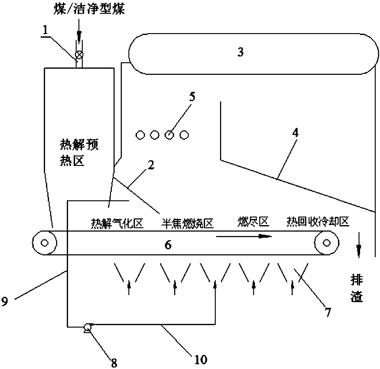
[0068] This embodiment part provides a kind of layer fired boiler, such as figure 2 As described above, the furnace body of the layer-fired boiler includes a first cavity and a second cavity connected at the bottom; the top and / or side of the first cavity is provided with a coal filling port 1, and the interior of the first cavity is In the pyrolysis preheating zone, the side of the furnace wall away from the side of the steam drum in the first cavity is inclined; a linear partition 2 is arranged inside the second cavity, and the linear partition 2 is connected to the first The cavity is connected to the inner wall of the second cavity at the connection part of the second cavity, the side of the partition near the first cavity is a pyrolysis gasification zone, and the other side is a semi-coke combustion zone; the second cavity A steam drum 3 is arranged on the top of the body, and a rear arch 4 is arranged on the furnace wall of the second cavity below the steam drum. Outle...
Embodiment 3
[0077] This embodiment partly provides a layer-fired boiler, the furnace body of the layer-fired boiler is divided into a first cavity and a second cavity by a partition plate; the top of the first cavity is provided with a coal filling port 1 , the inside of the first cavity is a pyrolysis preheating zone; the inside of the second cavity is provided with a broken-line partition 2, and the broken-line partition 2 is connected to the bottom of the regional partition plate, and the partition The side of the plate close to the first chamber is the pyrolysis gasification area, and the other side is the semi-coke combustion area; the top of the second chamber is provided with a steam drum 3, and the bottom of the steam drum is provided with a rear wall on the furnace wall of the second chamber. Arch 4, the space between the rear arch 4 and the connection between the first cavity and the second cavity is provided with an overfire tuyere 5;
[0078] The lower part of the first cavity...
PUM
 Abstract
Description
Claims
Application Information
 - R&D
- Intellectual Property
- Life Sciences
- Materials
- Tech Scout
- Unparalleled Data Quality
- Higher Quality Content
- 60% Fewer Hallucinations
Browse by: Latest US Patents, China's latest patents, Technical Efficacy Thesaurus, Application Domain, Technology Topic, Popular Technical Reports.
© 2025 PatSnap. All rights reserved.Legal|Privacy policy|Modern Slavery Act Transparency Statement|Sitemap|About US| Contact US: help@patsnap.com