
Fiber grating-based spectrum detecting device

A spectrum detection and fiber grating technology, which is applied in the field of fiber grating-based spectrum detection devices, can solve problems affecting the normal operation of the system and measurement errors, and achieve the effects of controlling volume and cost, improving resolution, and excellent performance

Pending Publication Date: 2019-03-29
MINNAN NORMAL UNIV
View PDF0 Cites 5 Cited by
  • Summary
  • Abstract
  • Description
  • Claims
  • Application Information

AI Technical Summary

Problems solved by technology

This kind of spectrometer strictly places each key module. Once the spectrometer is moved or vibrated, it is easy to cause measurement errors and affect the normal operation of the system; therefore, a reasonable solution is needed to solve the above problems

Method used


Image

  • Fiber grating-based spectrum detecting device
  • Fiber grating-based spectrum detecting device

Examples


Embodiment Construction

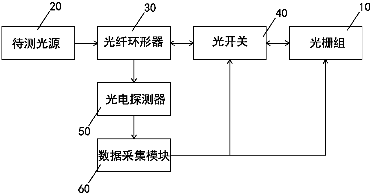
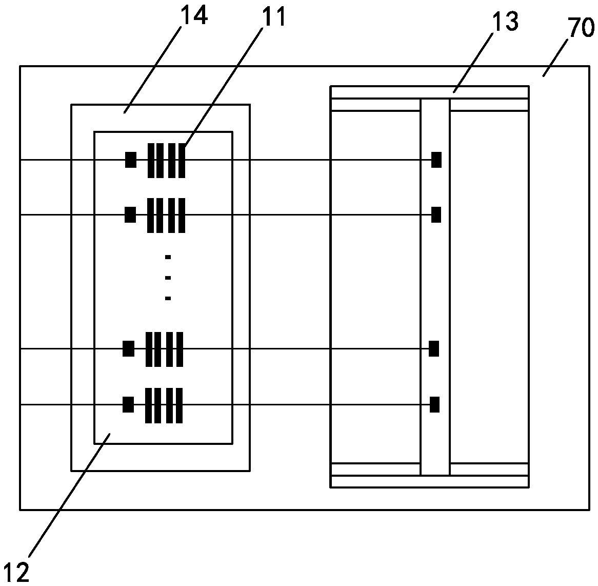
[0024] Examples, see figure 1 and figure 2 As shown, a fiber grating-based spectral detection device of the present invention includes a grating group 10, a light source to be measured 20, an optical fiber circulator 30, a 1×N optical switch 40, a high-speed PIN photodetector 50 and a data acquisition module 60 , the grating group 10 includes N gratings 11, an aluminum block 12 engraved with N V-shaped grooves, an electronically controlled precision translation stage 13 and a temperature control module 14 installed on the same base 70, and the N gratings One end of 11 is respectively fixed on the V-shaped groove, and the other end is respectively fixed on the precise translation platform 13, and described data acquisition module 60 comprises data acquisition card and computer, and described data acquisition card converts voltage signal into digital signal, so The computer connects the data acquisition card and the optical switch 40 to control the acquisition time of the data...


PUM


Abstract

The invention discloses a fiber grating-based spectrum detecting device. The spectrum detecting device comprises a grating group, a light source to be tested, a fiber circulator, a 1 x N optical switch, a photodetector, and a data acquisition module. An output light signal of the light source to be tested enters terminal 1 of the fiber circulator. Terminal 2 of the fiber circulator is connected toan input end of the optical switch. N output ends of the optical switch are connected to one ends of the N gratings. Signals reflected by the gratings enter terminal 3 of the fiber circulator throughthe optical switch. The terminal 3 of the fiber circulator is connected to an input end of the photodetector. An output end of the photodetector is connected with an input end of the data acquisitionmodule. An control end of the data acquisition module is connected to an switching control end of the optical switch. Switching the optical switch to process the signals collected on each grating anddisplay a signal of a spectrum of the light source to be tested. The fiber grating-based spectrum detecting device can meet different requirements and has the advantages that measurement errors caused by conveyance or vibration are avoided, the resolution of a spectrograph is improved by cooperation of coarse adjustment and fine adjustment.

Description

technical field [0001] The invention relates to a spectrum detection device based on a fiber grating. Background technique [0002] A spectrometer is a scientific instrument that decomposes complex light into spectral lines. It is composed of a prism or a diffraction grating. The spectrometer can be used to measure the light reflected from the surface of an object; the spectrometer captures, displays and analyzes light information to detect objects. This technology is widely used in the detection of air pollution, water pollution, food hygiene, metal industry, etc.; the working principle of commonly used spectrometers is generally that the spectral lines of different wavelengths are separated in space by diffraction gratings. The upper and lower parts are separated, and the spectral lines of different wavelengths are irradiated into the linear array photodetector, and the spectrum of the light source to be measured is obtained through subsequent signal processing. The key m...

Claims


Application Information

Patent Timeline
Patent Type & Authority Applications(China)
IPC IPC(8): G01J3/28G01J3/02
CPCG01J3/0218G01J3/28
Inventor 陈福昌黄国豪余超群张仁凤何志民黄成李游丁灿徐建武林莉珍
Owner MINNAN NORMAL UNIV
Learn More