Motor noise reduction structure
A technology of motors and motor brackets, applied in the field of electric motors, can solve problems such as equipment noise, vibration generated by motor operation, unbalanced load quality, etc., to achieve the effect of eliminating noise and avoiding direct rigid contact
- Summary
- Abstract
- Description
- Claims
- Application Information
AI Technical Summary
Problems solved by technology
Method used
Image
Examples
Embodiment 1
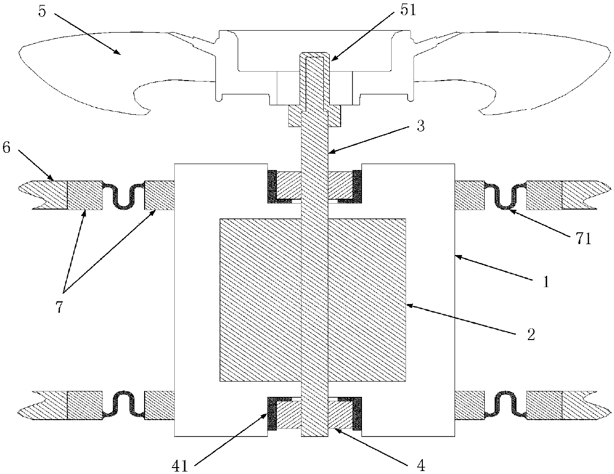
[0035] figure 1 It shows a specific embodiment 1 of a motor noise reduction structure of the present invention, which mainly includes a motor, a load 5, a motor bracket 6, and a flexible isolation assembly. The flexible isolation assembly at least includes a reinforced flexible connection part 7 and a flexible deformation part 71 .
[0036] The motor of this embodiment includes a stator 1 , an inner rotor 2 , a rotating shaft 3 and a bearing 4 .
[0037] The inner rotor 2 is sheathed and fixed on the rotating shaft 3, and the two ends of the rotating shaft 3 are fixedly connected with the stator 1 through a bearing 4 respectively.
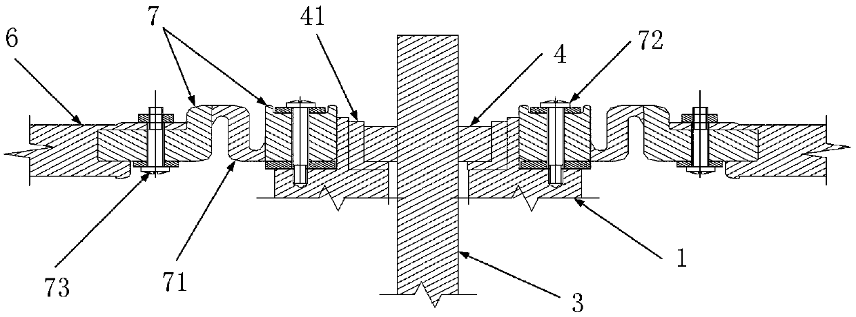
[0038] See attached figure 2 , the enhanced flexible connector 7 has two independent parts, one of which is fixed on the stator 1 through a connecting bolt 1 72, and the other part is fixed on the motor bracket 6 through a connecting bolt 2 73, the The flexible deformation member 71 is fixedly connected between the two parts. Wherein, in order...
Embodiment approach
[0041] in the attached figure 1 , as another preferred embodiment of the present invention, the flexible isolation assembly further includes a load-bearing flexible isolation sleeve / cap 51 made of a flexible material. The load flexible isolation sleeve / cap 51 is sleeved on the power output end of the rotating shaft 3 of the motor, and the load 5 is sleeved on the load flexible isolation sleeve / cap 51 with an interference fit. The load flexible isolation sleeve / cap 51 has at least two functions: one of them is used to isolate the vibration generated when the load 5 rotates, so as to avoid transmission to the rotating shaft 3; The center is elastically deformed by the extrusion of the centrifugal force of the load, and the auxiliary load 5 automatically realizes the dynamic balance adjustment. That is to say, the use of the load flexible isolation sleeve / cap 51 of the present invention can save the dynamic balance debugging process in the product manufacturing process. The latt...
Embodiment 2
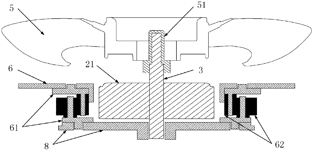
[0045] attached image 3 It shows the second specific embodiment of a motor noise reduction structure of the present invention, which mainly includes a motor, a load 5, a motor bracket 6, a motor fixing member 8, and a flexible isolation assembly. The flexible isolation assembly at least includes a bracket connector 61 and a flexible connector 62 .
[0046] The motor of this embodiment includes a stator (not shown in the figure), an outer rotor 21 and a rotating shaft 3 .
[0047] The outer rotor 21 is sheathed and fixed on the rotating shaft 3, and supported on the stator and the motor fixing member 8 through bearings (not shown in the figure) respectively.
[0048] Two bracket connecting parts 61 are provided between the motor bracket 6 and the motor fixing part 8 . The cross-section of the support connector 61 is roughly "L"-shaped, a protrusion or flange is provided on one extension of the "L" shape, and the flexible connector 62 is provided on both sides of the other exte...
PUM
 Abstract
Description
Claims
Application Information
 - R&D
- Intellectual Property
- Life Sciences
- Materials
- Tech Scout
- Unparalleled Data Quality
- Higher Quality Content
- 60% Fewer Hallucinations
Browse by: Latest US Patents, China's latest patents, Technical Efficacy Thesaurus, Application Domain, Technology Topic, Popular Technical Reports.
© 2025 PatSnap. All rights reserved.Legal|Privacy policy|Modern Slavery Act Transparency Statement|Sitemap|About US| Contact US: help@patsnap.com


