Supercharge Your Innovation With Domain-Expert AI Agents!

Ball-end milling cutter related to steep vertical surface die machining

A technology of mold processing and ball end milling cutter, which is applied in the direction of milling cutter, metal processing equipment, manufacturing tools, etc., can solve the problems of uneven acceptance of cutting edge line, short service life of cutting tool, low processing efficiency, etc., and achieve uniform force , High chip removal efficiency, and the effect of tool chatter suppression

Inactive Publication Date: 2019-04-02
HARBIN UNIV OF SCI & TECH
View PDF9 Cites 0 Cited by
  • Summary
  • Abstract
  • Description
  • Claims
  • Application Information

AI Technical Summary

Problems solved by technology

The existing ball-nose milling cutter has low processing efficiency for machining steep vertical molds, the chip removal is not smooth, the cutting edge line is uneven, and the tool life is short

Method used


Image

  • Ball-end milling cutter related to steep vertical surface die machining
  • Ball-end milling cutter related to steep vertical surface die machining

Examples


Embodiment Construction

[0014] Embodiments of the present invention will be further described below in conjunction with the accompanying drawings.

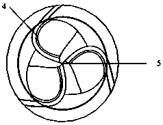
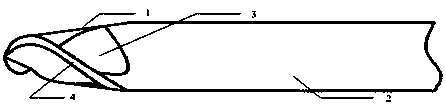
[0015] See attached figure 1 , attached figure 2 , The present invention, regarding the ball end milling cutter for steep vertical surface mold processing: includes a ball head 1, a shank 2, a tooth gap 3, a peripheral cutting edge 4 and a ball head vertex 5. The ball head 1 is fixedly connected with the shank 2, and the ball head 1 is provided with three evenly distributed peripheral cutting edges 4, the three peripheral cutting edges 4 intersect at the ball head vertex 5, and there are tooth gaps 3 between adjacent peripheral cutting edges 4 , the taper of the cutter body of the ball head 1 is 4°.

[0016] In the present invention, regarding the ball end milling cutter for mold processing with steep elevations, the tooth gap 3 is located behind the peripheral cutting edge 4 in the rotation direction.

[0017] In the present invention, the ball head...


PUM


Abstract

The invention discloses a ball-end milling cutter related to steep vertical surface die machining, and solves the problems that when an existing cutter machines a steep vertical surface, the efficiency is relatively low, cutting edge lines of the cutter is unevenly stressed, the probability of unsmooth chip removal is high and the service life of the cutter is shortened. The ball-end milling cutter consists of a ball end 1, a handle 2, a tooth gap 3, peripheral cutting edges 4 and a ball end point 5. The ball-end milling cutter is characterized in that the uniformly distributed peripheral cutting edges are intersected at the ball end point, so that edge lines in the machining process are evenly stressed, the transverse edge strength of the center of the ball end is improved, the milling efficiency is improved, the service life is prolonged, and the durability of the cutter is improved. The groove type of the tooth gap adopts an open structure, the open tooth gap structure facilitates chip removal, the chip containing space is larger, and the chip removal efficiency is improved. Compared with the prior art, the ball-end milling cutter has the following advantages of reasonable structural design, uniformity of the stress on the edge lines, high ball end strength, small chip impact, high chip removal efficiency and larger chip containing space.

Description

technical field [0001] The invention relates to the technical field of machining cutting tools, in particular to a ball-end milling cutter for steep-surface mold processing. Background technique [0002] The ball end milling cutter is a tool with a blade similar to a ball end and assembled on a milling machine for milling various curved surfaces and arc grooves. Ball end milling cutter is also called R cutter. The existing ball-nose milling cutter has low processing efficiency for processing steep vertical molds, the chip removal is not smooth, the cutting edge line is not uniform, and the cutting tool life is short. Contents of the invention [0003] The technical problem to be solved by the present invention is to overcome the above-mentioned deficiencies in the prior art, and to provide a ball end milling cutter for processing steep molds. Its structural design is reasonable, the force on the edge line is uniform, the ball head has high strength, the chip impact is sm...

Claims


Application Information

Patent Timeline
Patent Type & Authority Applications(China)
IPC IPC(8): B23C5/10B23C5/16
CPCB23C5/1018B23C5/165
Inventor 姜彦翠仇焱崔健
Owner HARBIN UNIV OF SCI & TECH
Features
  • R&D
  • Intellectual Property
  • Life Sciences
  • Materials
  • Tech Scout
  • Unparalleled Data Quality
  • Higher Quality Content
  • 60% Fewer Hallucinations
Learn More