LED chip soldering device

A LED chip and soldering technology, which is applied to tin feeding devices, welding equipment, metal processing equipment, etc., can solve the problem of low welding efficiency and achieve the effect of not being easy to waste

Active Publication Date: 2019-04-02
TIANJIN MONXYUAN TECH
View PDF7 Cites 4 Cited by
  • Summary
  • Abstract
  • Description
  • Claims
  • Application Information

AI Technical Summary

Problems solved by technology

The heart of the LED is a semiconductor chip. One end of the chip is attached to a bracket, one end is the negative pole, and the other end is connected to the positive pole of the power supply, so that the entire chip is encapsulated by epoxy resin. The LED chip and the wire are mainly connected by soldering. Together, the current soldering mechanism generally uses manual tin spot auxiliary welding, and the welding efficiency is not high

Method used


Image

  • LED chip soldering device
  • LED chip soldering device
  • LED chip soldering device

Examples


Embodiment Construction

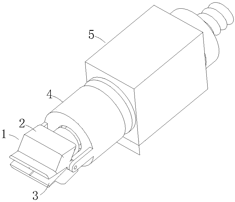
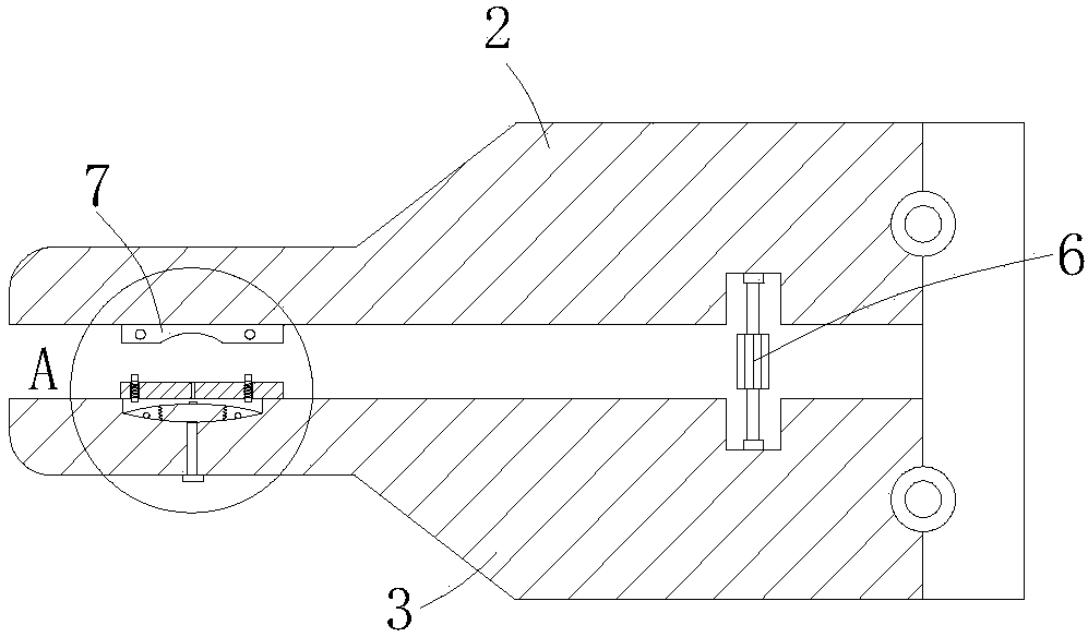
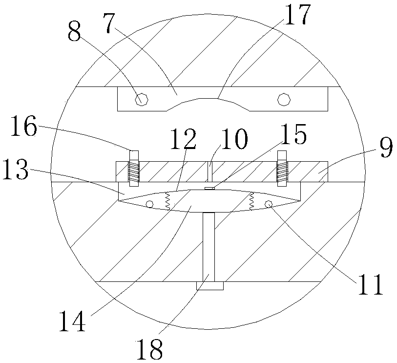
[0016] Such as Figure 1 to Figure 3 As shown, a LED chip soldering device includes a soldering chuck 1, the soldering chuck 1 is composed of an upper chuck 2 and a lower chuck 3, and the tails of the upper chuck 2 and the lower chuck 3 are movably connected with a rotating sleeve 4. The rotary sleeve 4 is connected to the rotary cylinder 5, and the clamping cylinder 6 is connected between the upper chuck 2 and the lower chuck 3. The inner surface of the upper chuck 2 is provided with a heating plate 7, and the heating wire 8 is embedded in the heating plate 7. ;

[0017] The inner surface of the lower chuck 3 is provided with a welding station 9 corresponding to the electric heating plate 7, the middle part of the welding station 9 is provided with a tin outlet hole 10, and the inside of the lower chuck 3 is provided with a tin storage chamber connected with the tin outlet hole 10. Heating wire 11 is laid on the bottom of the tin storage chamber, and an arc-shaped metal cove...


PUM


Abstract

The invention relates to an LED chip soldering device. The LED chip soldering device comprises a soldering chuck, wherein the soldering chuck is composed of an upper chuck body and a lower chuck body;a clamping cylinder is connected between the upper chuck body and the lower chuck body; an electric heating plate is arranged on the inner side surface of the upper chuck body; an electric heating wire is embedded in the electric heating plate; a welding table is arranged on the inner side surface of the lower chuck body; a tin outlet hole is formed in the middle of the welding table; a tin storage cavity communicating with the tin outlet hole is formed in the lower chuck body; an electric heating wire is laid at the bottom of the tin storage cavity; an arc-shaped metal cover plate is arranged in the tin storage cavity; the arc-shaped metal cover plate is buckled in the tin storage cavity to divide the tin storage cavity into an upper tin storage cavity body and a lower tin storage cavitybody; an opening for enabling the upper tin storage cavity body and the lower tin storage cavity body to communicate is formed in the arc-shaped metal cover plate; and a mounting hole is formed in the welding table, ejecting columns are arranged in the mounting hole, a spring is fixed in the mounting hole, and the ejecting columns extend into the upper tin storage cavity body after penetrating through the spring and corresponds to the surface of the arc-shaped metal cover plate. The LED chip soldering device has the advantages that a limited amount of tin in a molten state can be supplied atany time, and waste is avoided.

Description

technical field [0001] The invention relates to LED chip processing equipment, in particular to an LED chip soldering device. Background technique [0002] LED is also called light emitting diode. Its basic structure is a piece of electroluminescent semiconductor material, a solid-state semiconductor device that can directly convert electricity into light. Put it on a shelf with leads, and then seal it with epoxy resin around it to protect the inner core wire, so the LED has good shock resistance. The heart of the LED is a semiconductor chip. One end of the chip is attached to a bracket, one end is the negative pole, and the other end is connected to the positive pole of the power supply, so that the entire chip is encapsulated by epoxy resin. The LED chip and the wire are mainly connected by soldering. Together, the current soldering mechanism generally uses manual tin spot auxiliary welding, and the welding efficiency is not high. Contents of the invention [0003] Th...

Claims


Application Information

Patent Timeline
Patent Type & Authority Applications(China)
IPC IPC(8): B23K3/06
CPCB23K3/0615
Inventor 孟祥全
Owner TIANJIN MONXYUAN TECH
Why Eureka
Try Eureka