Multifunctional new energy charging pile

A charging pile and new energy technology, applied in the field of multifunctional new energy charging piles, can solve the problems of damage to the charging pile, accelerate the aging of the internal components of the charging pile, shorten the service life of the charging pile, etc., and achieve the effect of blocking sunlight and rain.

Inactive Publication Date: 2019-04-02
白雪
View PDF6 Cites 11 Cited by
  • Summary
  • Abstract
  • Description
  • Claims
  • Application Information

AI Technical Summary

Problems solved by technology

[0003] The purpose of the present invention is to provide a multi-functional new energy charging pile, which has the advantages of high-efficiency heat dissipation and buffering against car impacts, and solves the problem that if the high temperature cannot be dissipated in time, the aging of the internal components of the charging pile will be accelerated, and the charging pile will be shortened. The service life of the car, and the distance between the car and the charging pile is very close, if the driver accidentally hits the charging pile, it is easy to cause serious damage to the charging pile

Method used


Image

  • Multifunctional new energy charging pile
  • Multifunctional new energy charging pile
  • Multifunctional new energy charging pile

Examples


Embodiment 1

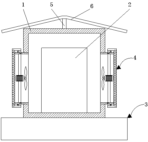
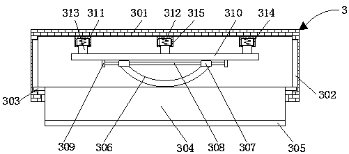
[0017] see Figure 1-3 , a multifunctional new energy charging pile, comprising a protective case 1, a support column 5 is fixedly connected to the center of the top of the protective case 1, a sunshade 6 is fixedly connected to the top of the support column 5, and the center of the top of the protective case 1 is fixedly connected There is a support column 5, and the top of the support column 5 is fixedly connected with a sunshade 6. By setting the support column 5 and the sunshade 6, the effect of blocking sunlight and rain is achieved. The bottom of the inner cavity of the protective shell 1 is fixedly connected with the charging pile body 2 The bottom of the protective case 1 is fixedly connected with an impact buffer mechanism 3, the impact buffer mechanism 3 includes a base 301, and both sides of the inner cavity of the base 301 are provided with slideways 302, and the inner cavity of the slideway 302 is slidably connected with a slide rod 303, and the sliding The side o...

Embodiment 2

[0019] see Figure 1-3, a multifunctional new energy charging pile, comprising a protective case 1, a support column 5 is fixedly connected to the center of the top of the protective case 1, a sunshade 6 is fixedly connected to the top of the support column 5, and the center of the top of the protective case 1 is fixedly connected There is a support column 5, and the top of the support column 5 is fixedly connected with a sunshade 6. By setting the support column 5 and the sunshade 6, the effect of blocking sunlight and rain is achieved. The bottom of the inner cavity of the protective shell 1 is fixedly connected with the charging pile body 2 The bottom of the protective case 1 is fixedly connected with an impact buffer mechanism 3, the impact buffer mechanism 3 includes a base 301, and both sides of the inner cavity of the base 301 are provided with slideways 302, and the inner cavity of the slideway 302 is slidably connected with a slide rod 303, and the sliding The side of...


PUM


Abstract

The invention discloses a multifunctional new energy charging pile which comprises a protective shell. The bottom of an inner cavity of the protective shell is fixedly connected with a charging pile body. The bottom of the protective shell is fixedly connected with an impact buffering mechanism. Heat dissipation mechanisms are arranged on the two sides of the protective shell. Through cooperationof the protective shell, the charging pile body, the impact buffering mechanism, a base, sliding ways, sliding rods, a buffering baffle, a rubber strip, an arc-shaped shock absorption board, movable sleeves, a connecting rod, fixed blocks, a supporting board, casing pipes, buffer springs, movable columns, sliding grooves, sliding blocks, the heat dissipation mechanisms, air pipes, pull rods, ventilators, clamping grooves, filter screens, press boards, pressure springs and clamping rods, the problems that if heat cannot be dissipated in time, aging of internal elements of the charging pile canbe accelerated, the service life of the charging pile is shortened, the distance between an automobile and the charging pile is short in the charging process, and if a driver accidentally impacts thecharging pile, the charging pile is likely to be seriously damaged are solved.

Description

technical field [0001] The invention relates to the technical field of charging piles, in particular to a multifunctional new energy charging pile. Background technique [0002] Since the first electric vehicle came out, rechargeable batteries have been used as its power source. For an electric vehicle, battery charging equipment is one of the indispensable systems. The battery charging equipment is called a charging pile. Its function It converts the electric energy of the grid into the electric energy of the electric vehicle battery. The function of the charging pile is similar to that of the fuel dispenser in the gas station. It can be fixed on the ground or wall, and installed in the parking lot or charging station of public buildings and residential areas. It can be used according to different The voltage level is for charging various types of electric vehicles. The input end of the charging pile is directly connected to the AC power grid, and the output end is equipped...

Claims


Application Information

Patent Timeline
Patent Type & Authority Applications(China)
IPC IPC(8): B60L53/302B60L53/31E01F15/14
CPCE01F15/146Y02T10/70Y02T10/7072Y02T90/12
Inventor 白雪
Owner 白雪
Why Eureka
Try Eureka